Upgrading from 2in pipe to 2-1/2in pipe.
Lets start from the beginning. I chose 2in inter-cooler piping for easy routing, cost and I was told it could reduce turbo lag time. When I initially started building my turbo setup in 2007, I was not able to bring my mx6 into our main shop due to it being to busy and the current management. Instead I had to do mock up in my garage with a 110v welder with flux core wire, a grinder and cut off disc and limited tools. I then brought these pipes to work and MIG welded them, proving a challenge as the metal was very thin and the mock up wasn’t cleanly done. This was my first time welding material this thin. While exterior wise they were displeasing, inside wise they held pressure and I was able to debur the inside welds.
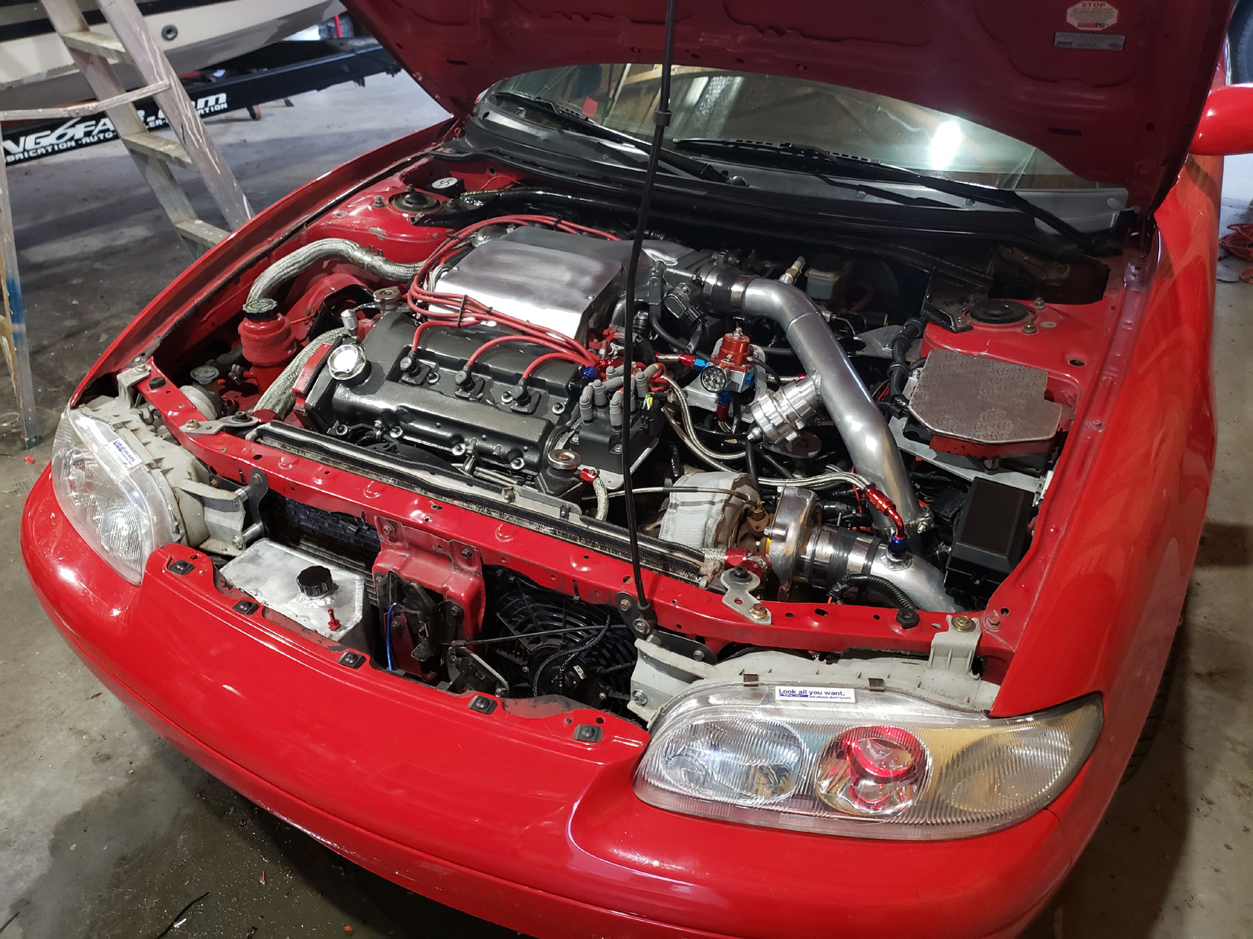
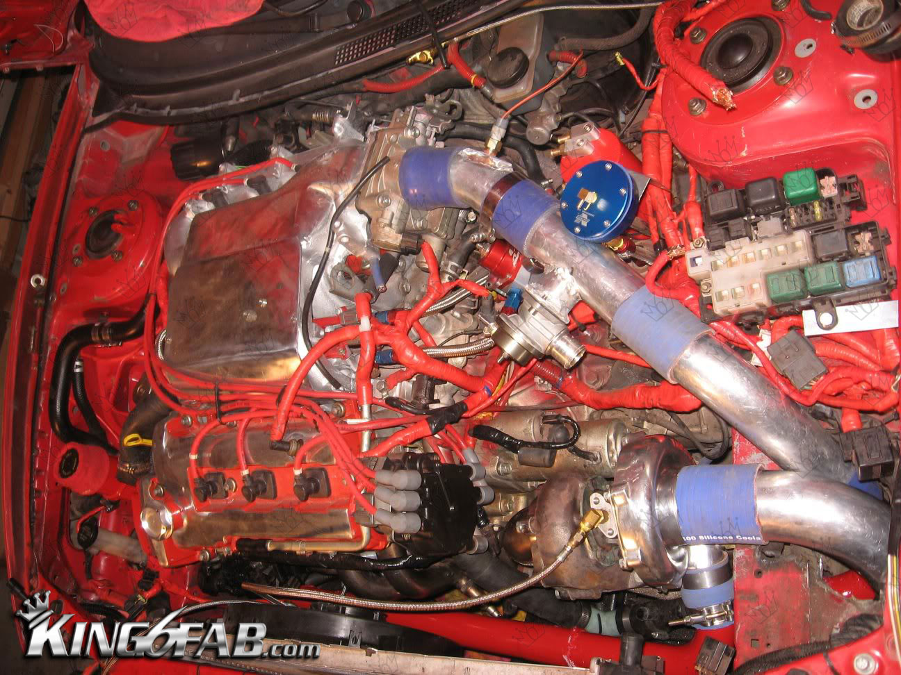
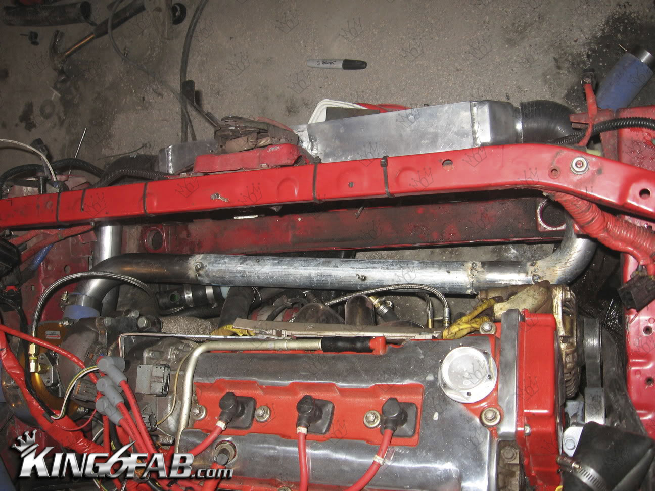
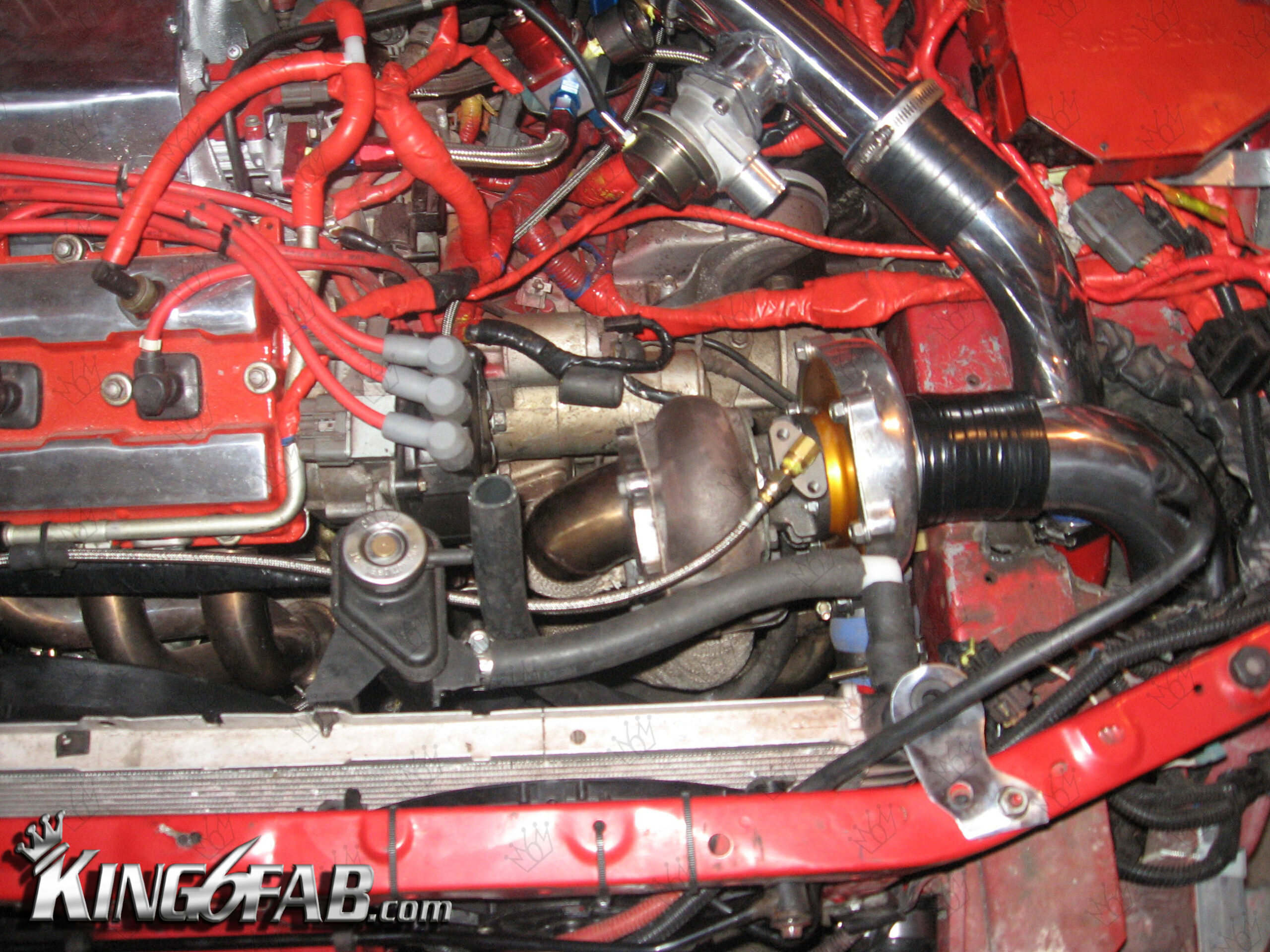
Below is how the pipes were ran. They started at the turbo 2in pipe from the 2in turbo compressor outlet, They ran to the inter-cooler where it transitioned with a 90deg coupler from 2in to 2.5in, Out the inter-cooler it transitioned from 2.5in to 2in once again, where it ran thru the driver side fender well and up thru the battery tray area where it again transitioned from 2in to 2.5in to the throttle body.

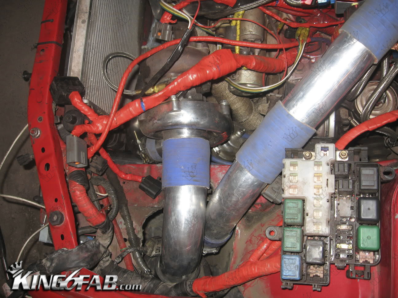


New 2.5in 16GA Aluminum Pipes
These pipes were bought from Ebay as a generic Inter-cooler build Kit
Enter 2018, the 2in inter-cooler pipes setup has always bothered me and I decided I can do them better ,increase turbo spool up and overall performance> One major issue is the radiator and fog-lights both have very limited room for the 2in piping alone, How was I going to fit 2.5in? This was a problem I would need to solve later, for now I need to make pipes.
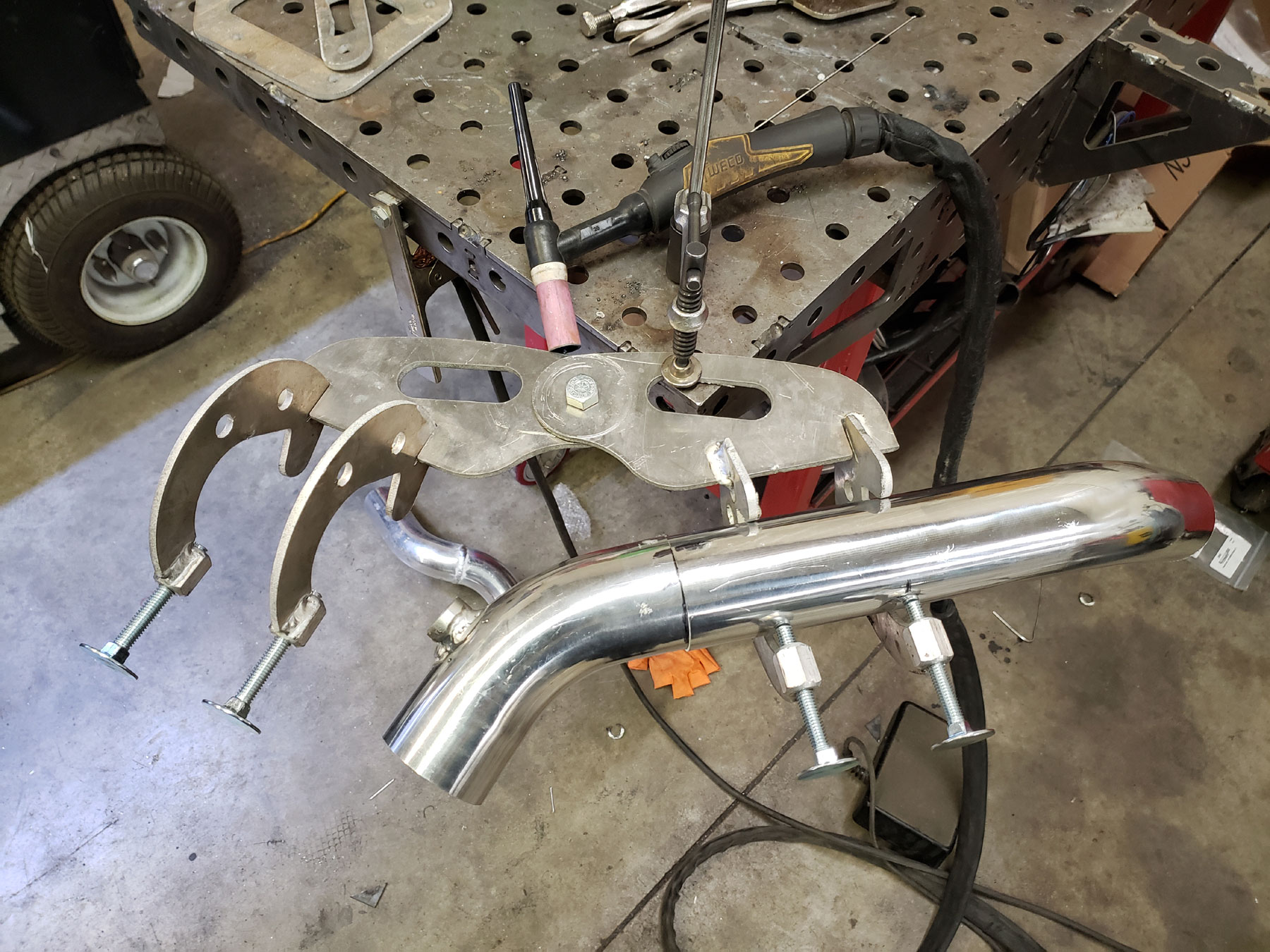
For these pipes I decided to CNC cut some fixtures to hold the pipes in position while I tacked them and welded them. The fixture could use some reworking as they are difficult to get positioned at certain angles. However as a third hand for holding the pipes while TIG welding they were very useful.

The layout for the pipes will basically be the same, except I will need to remove more material from the radiator core support to make clearance for the larger pipes.

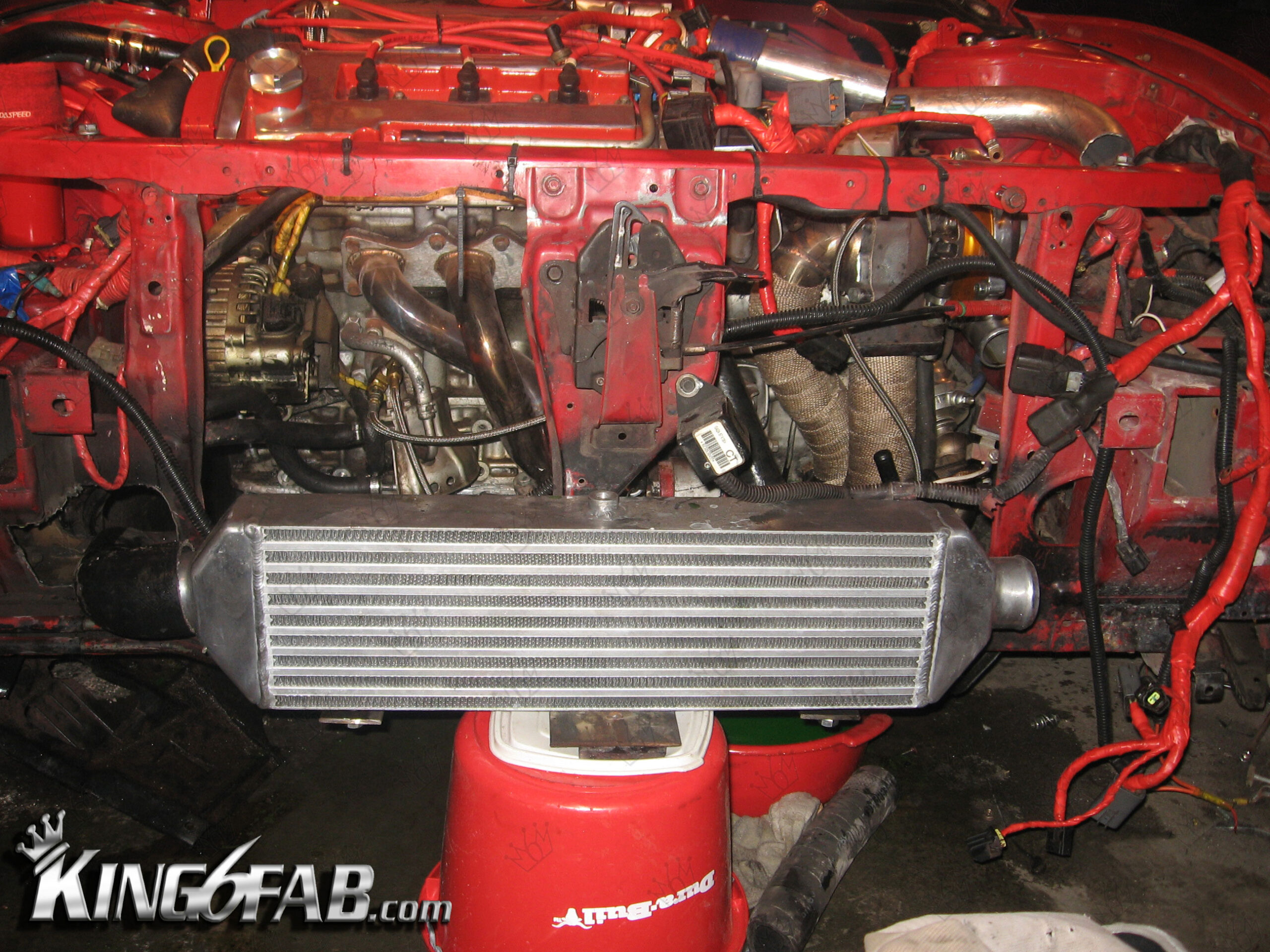
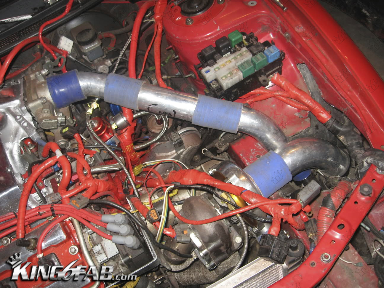
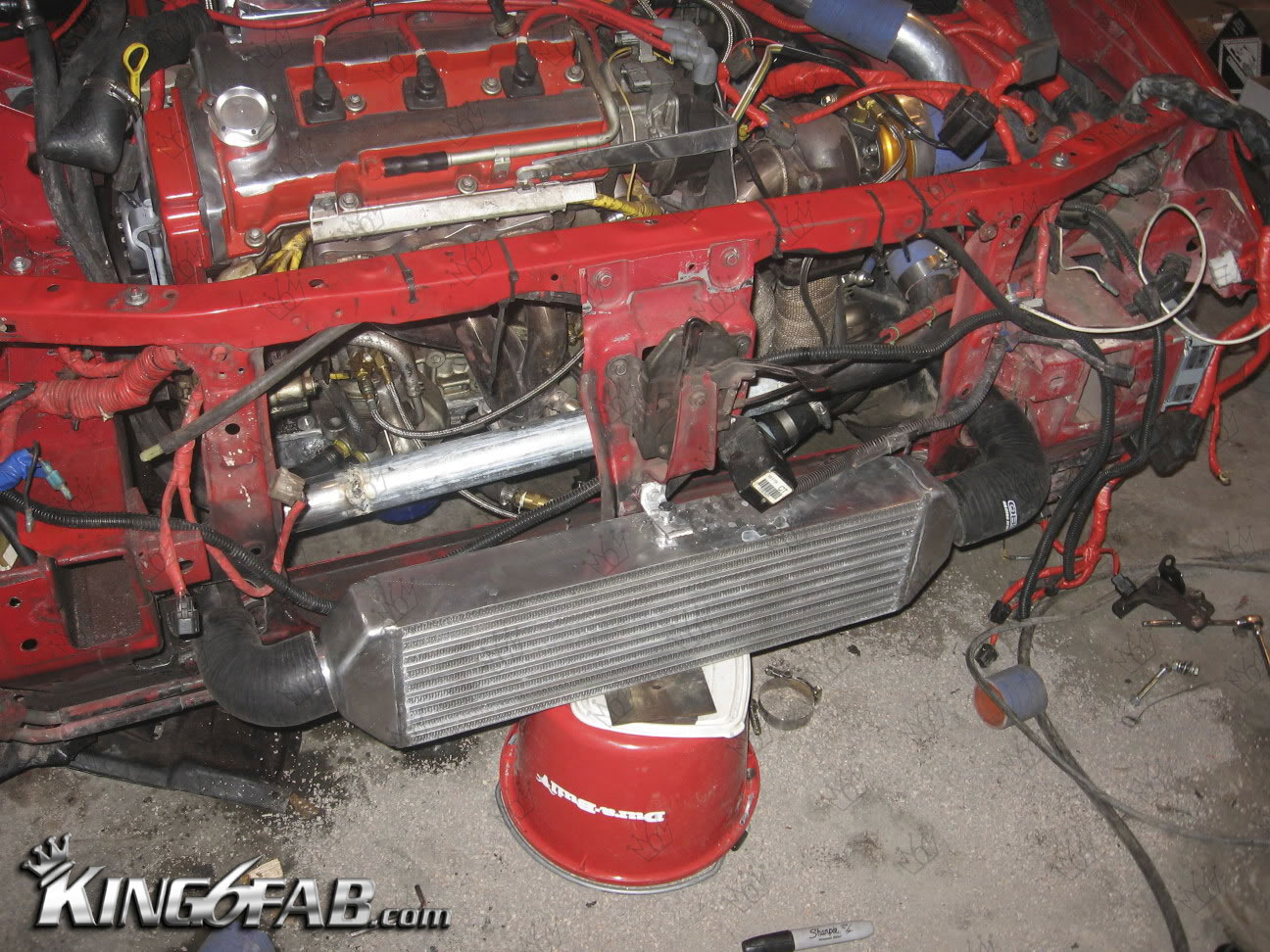
How the pipes are routed to the inter-cooler.
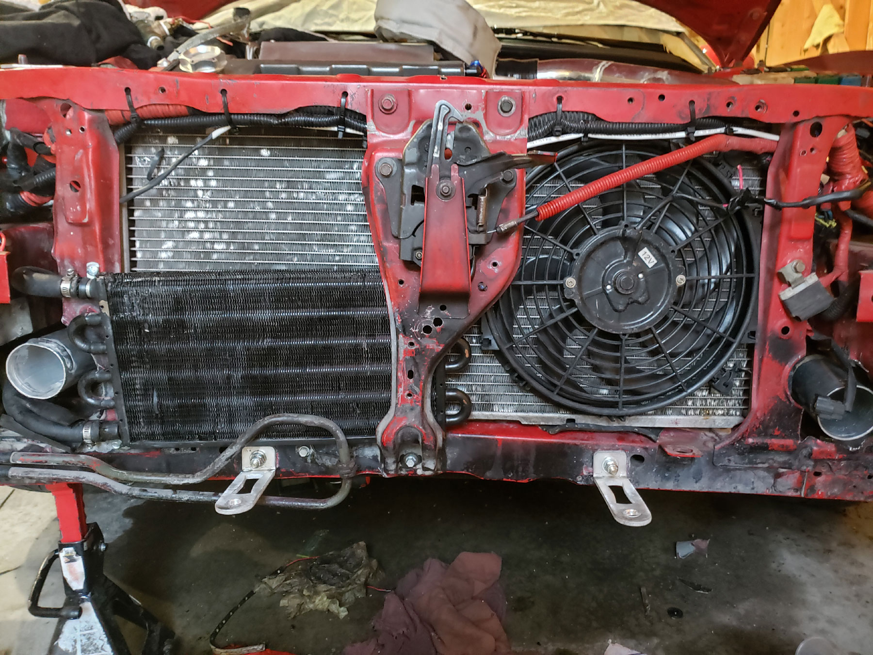

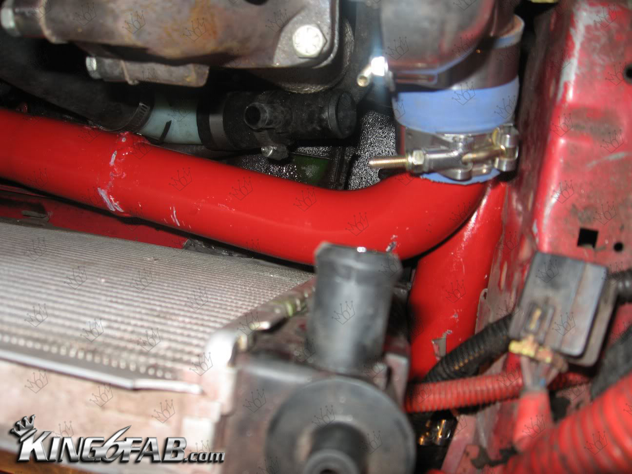
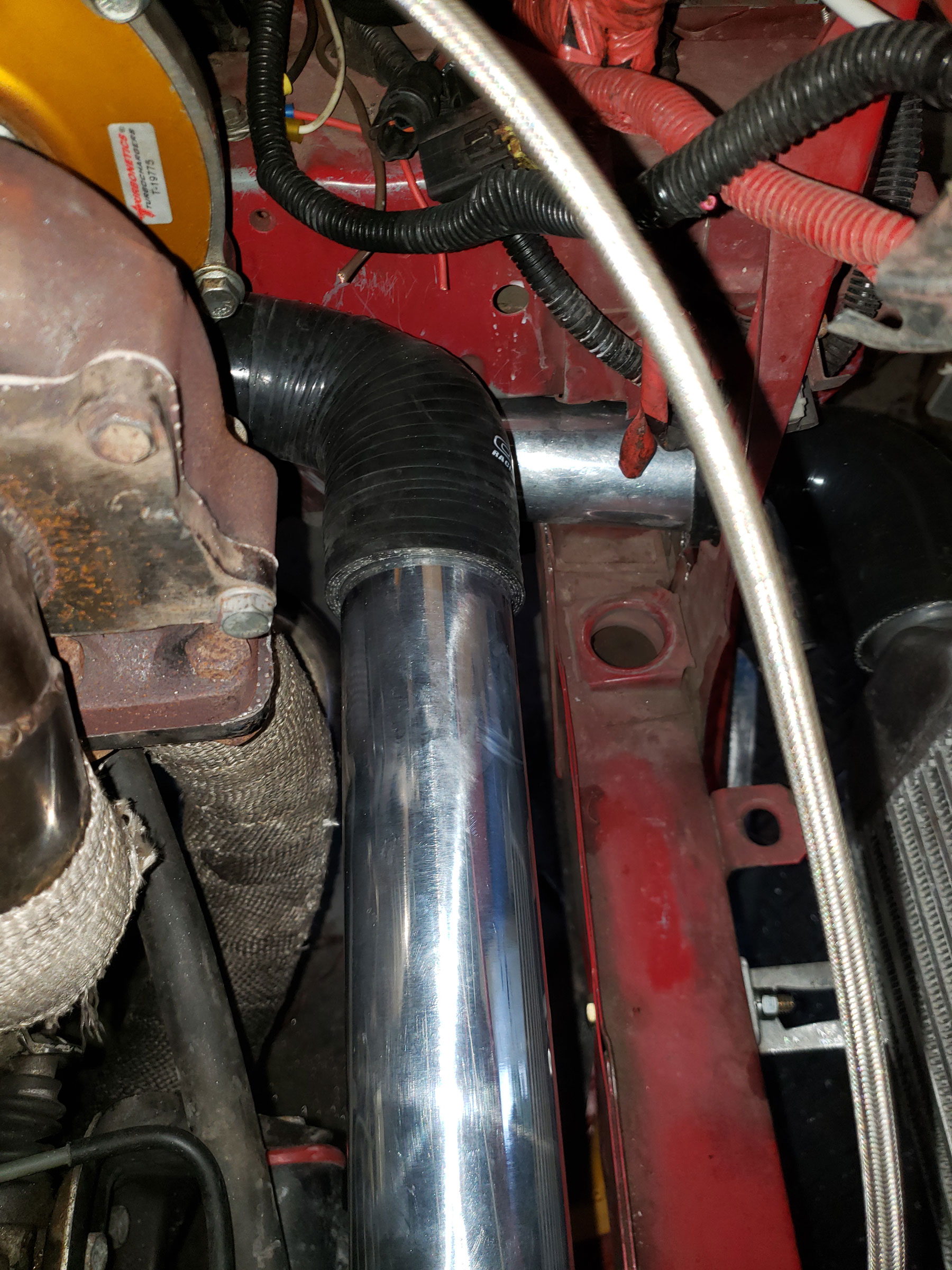
Here you can see the tight clearances using this diameter pipe using the same layout as the 2in pipe. To make things easy I used preformed couplers for the 90-degree connections.
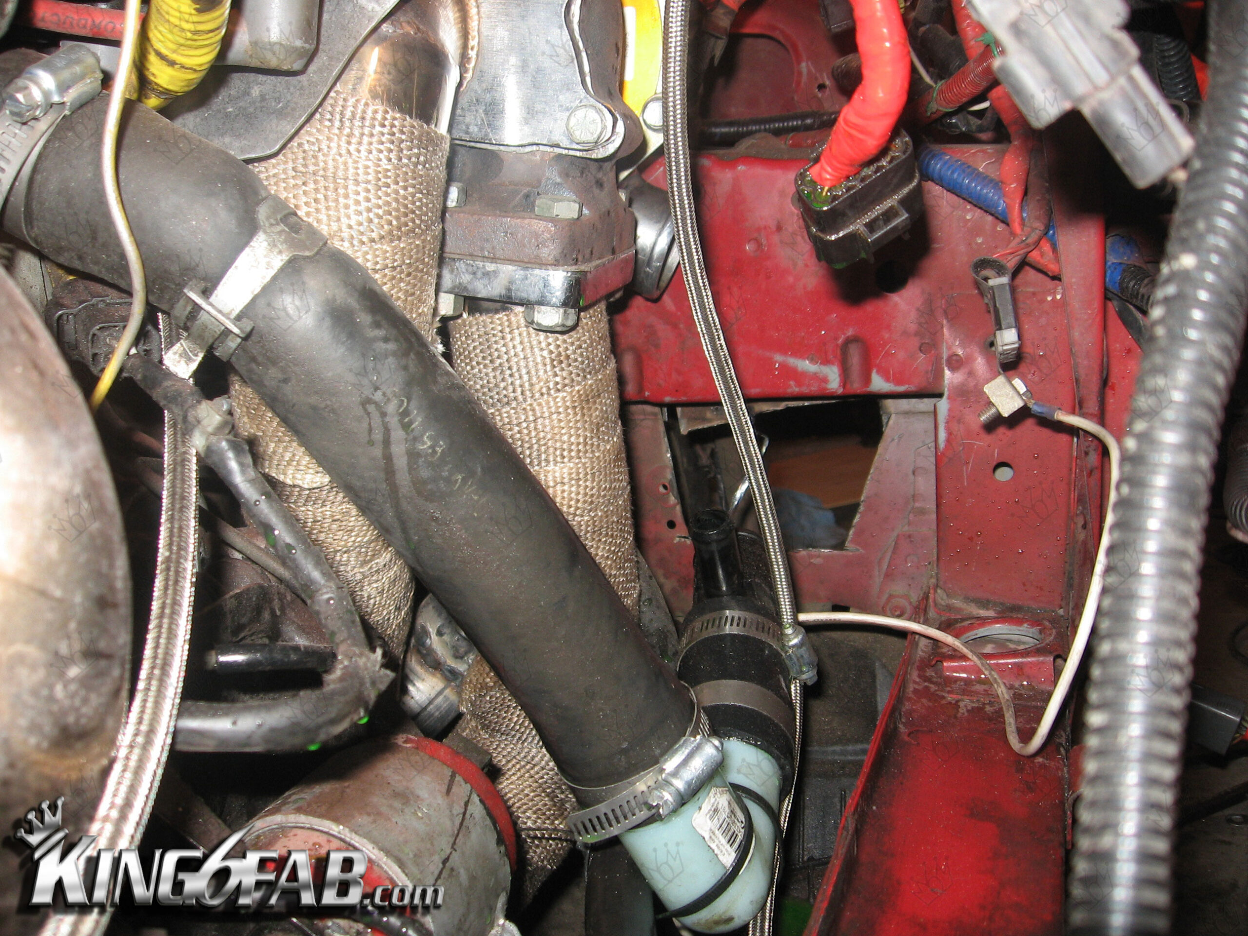
The amount of space between the radiator and the pipe. I would have preferred to make this a solid welded piece but getting it to fit with the radiator would have been nearly impossible. I may change this later with a custom radiator that will allow more space.
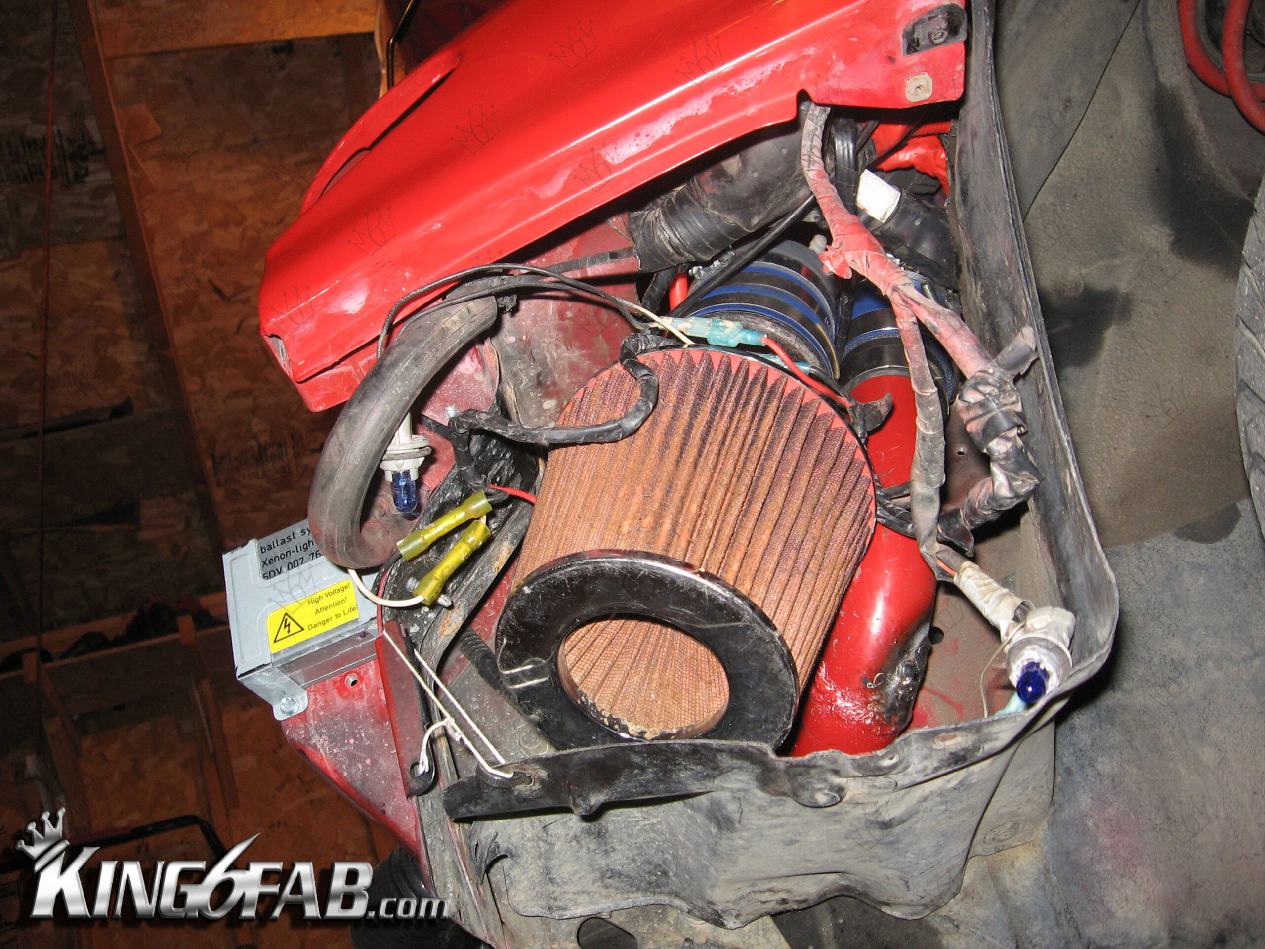
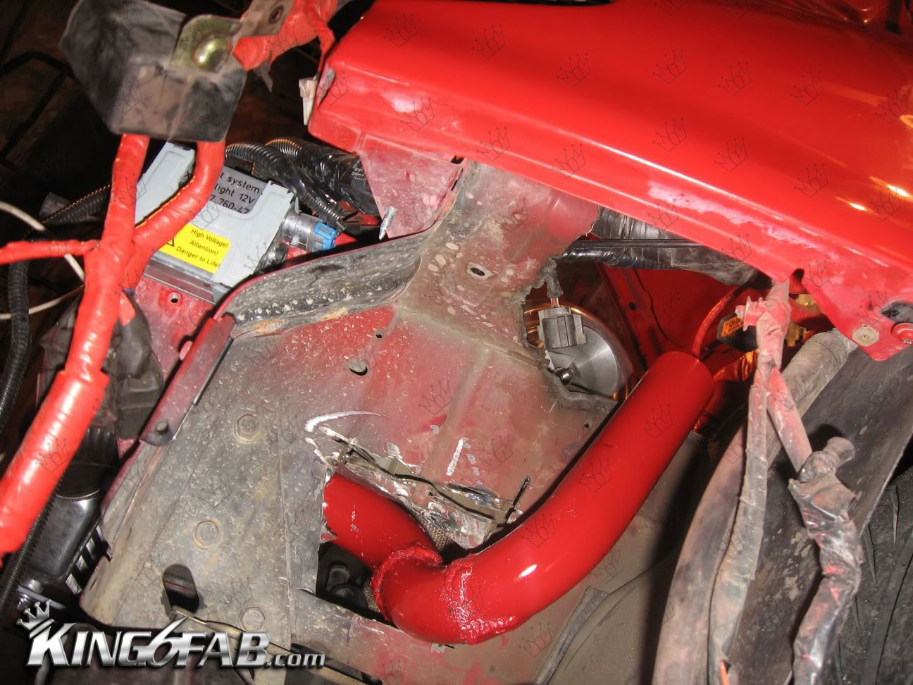
The hole in the fender well I had made in 2007 was very shotty, At the time I only had an angle grinder with a cut off disc. Idealy it should have been made with a 6in hole saw, but I didn’t have tools like that then. I decided to make a flange to bolt on to clean up the look somewhat.


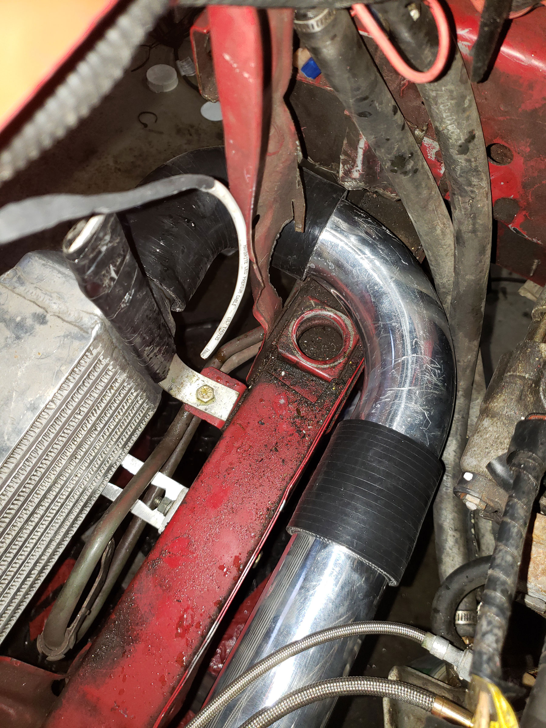
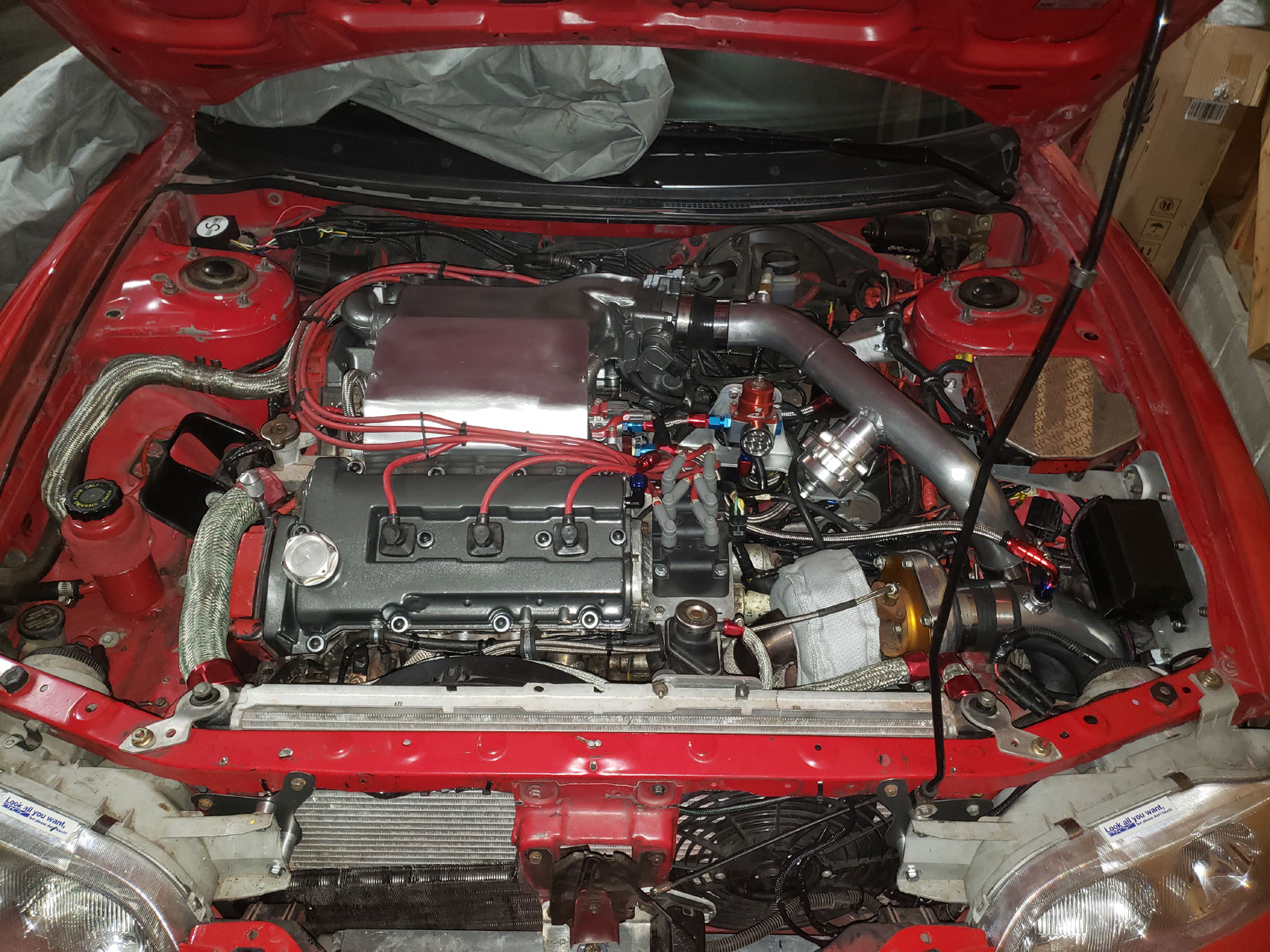
Pipe routing finished

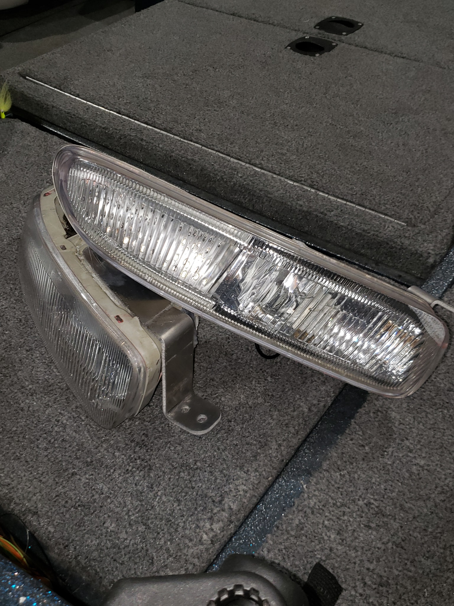
Foglights
The fog lights required extensive modification to make them fit with these new pipes. I didn’t get pictures of the extensive modification, but it required removing much of the enclosure on the back side, specifically the mounting stud area to decrease its depth. Doing this posed an issue for mounting the fog lights as the mounting stud was gone. The cap for the enclosure is well known to have stripped screws and or nut zerts. 2 out of 3 on mine were stripped or broken in some way, so I choose to cut the entire cap molding off and grind it flat to the surface. I then cut and bent aluminum brackets that doubled as a cap for the bulb inside and bracket for the fog light.

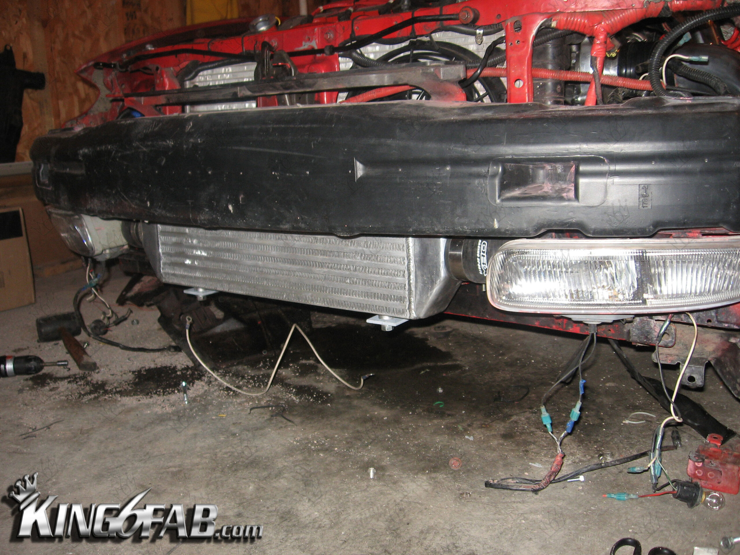
Finished Result of Inter-cooler in Bumper with fog lights.

Finished project, Next in 2021 I will be retrofitting a universal Griffin radiator to resolve some of the pipe clearances and help with cooling.