

Similar Posts
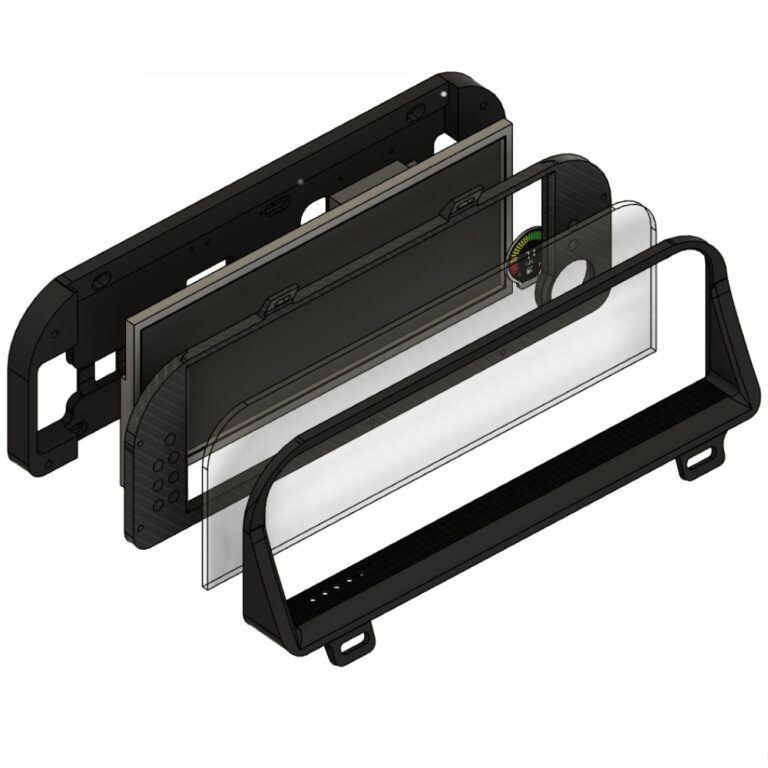
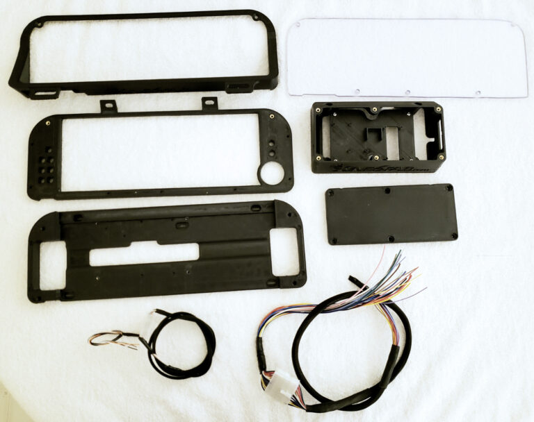
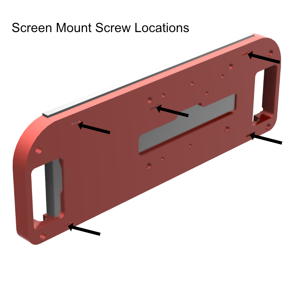
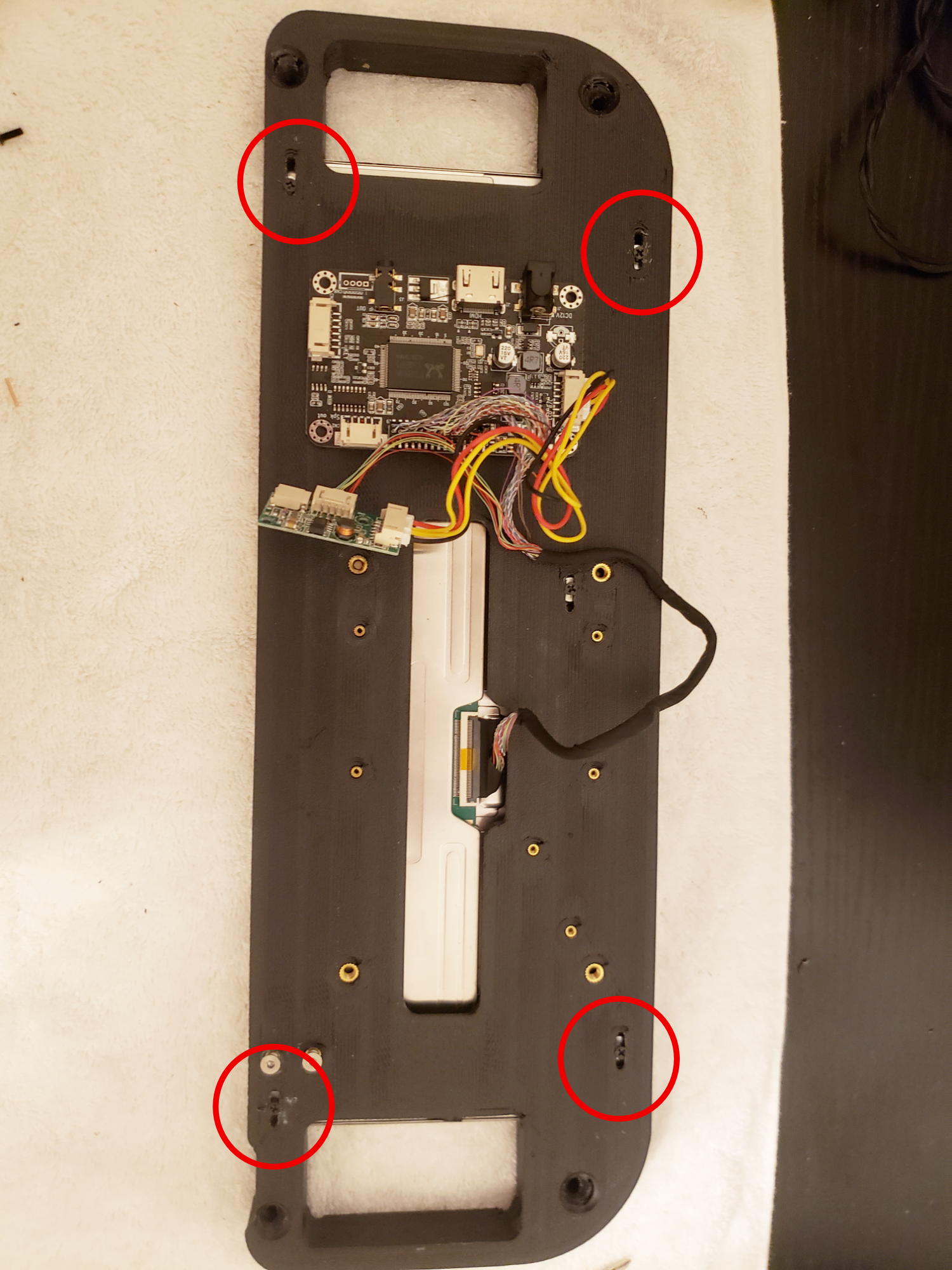
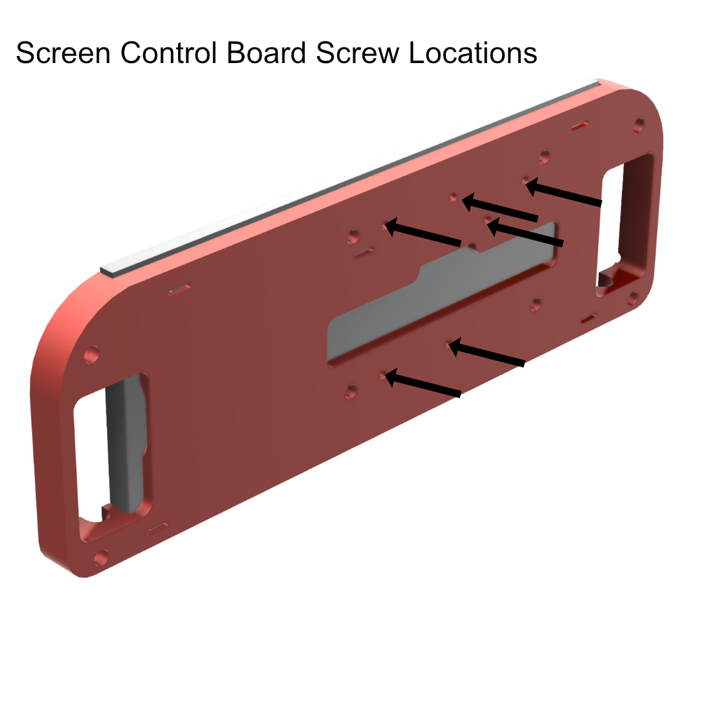
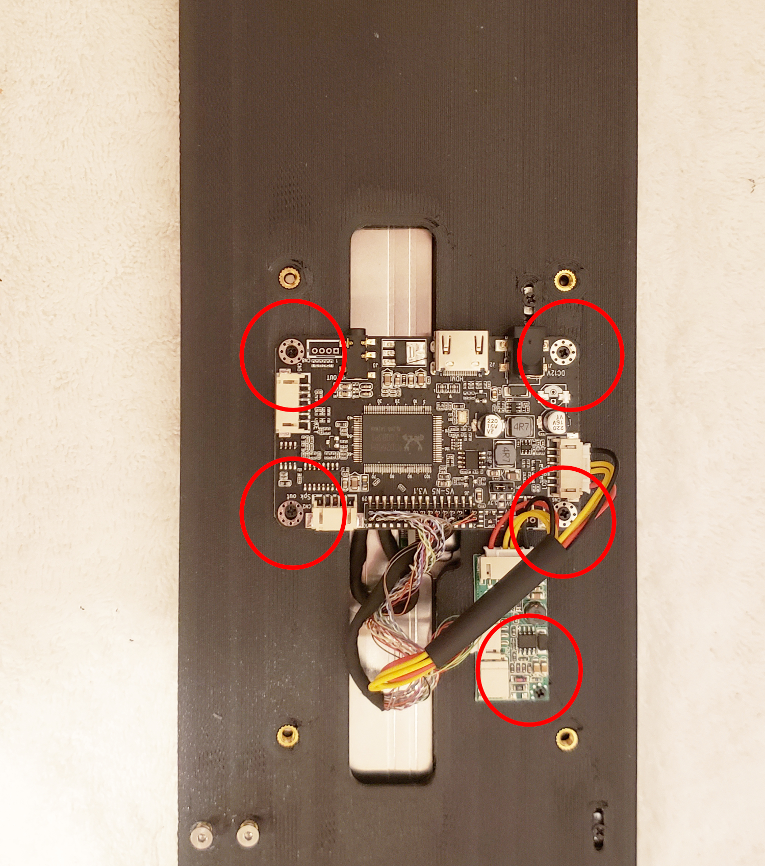
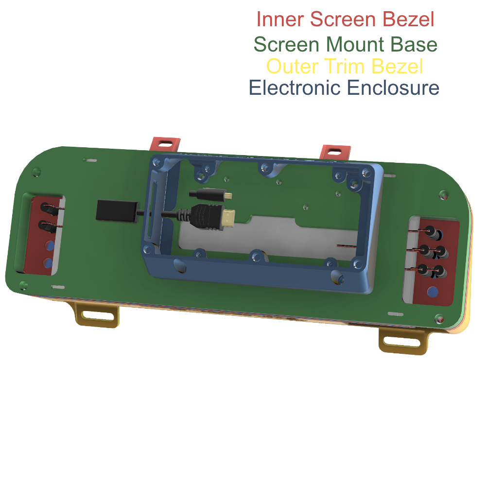
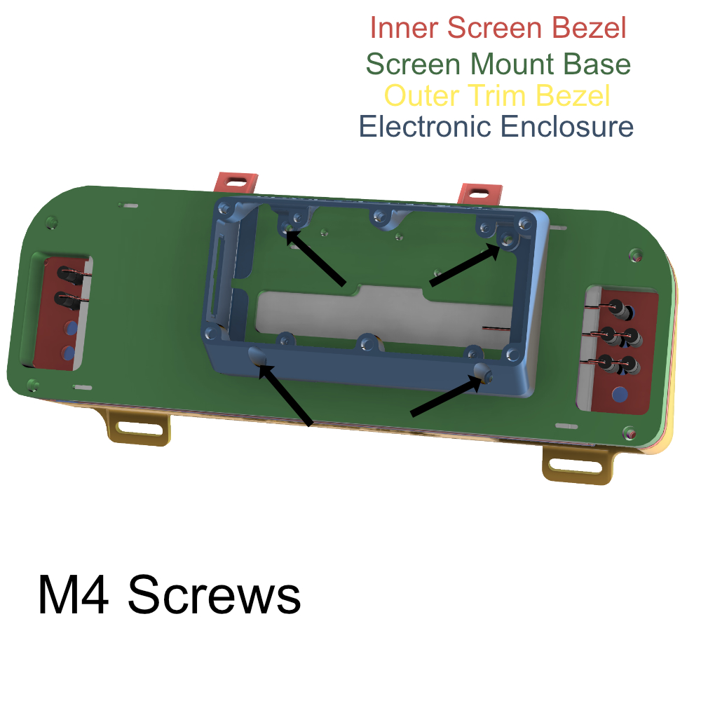
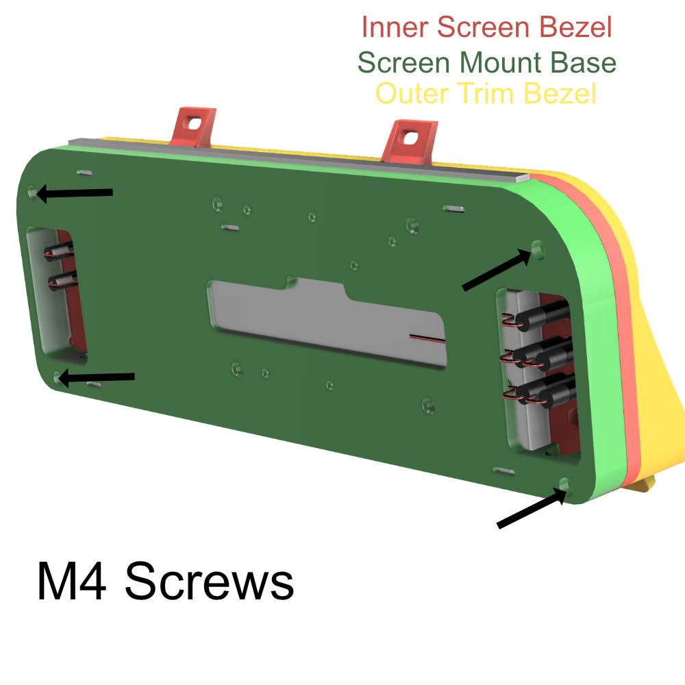
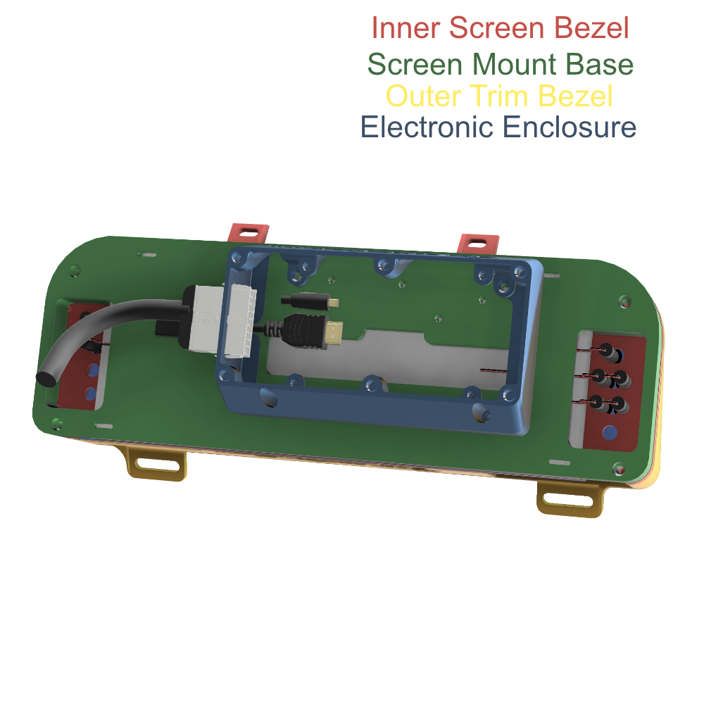
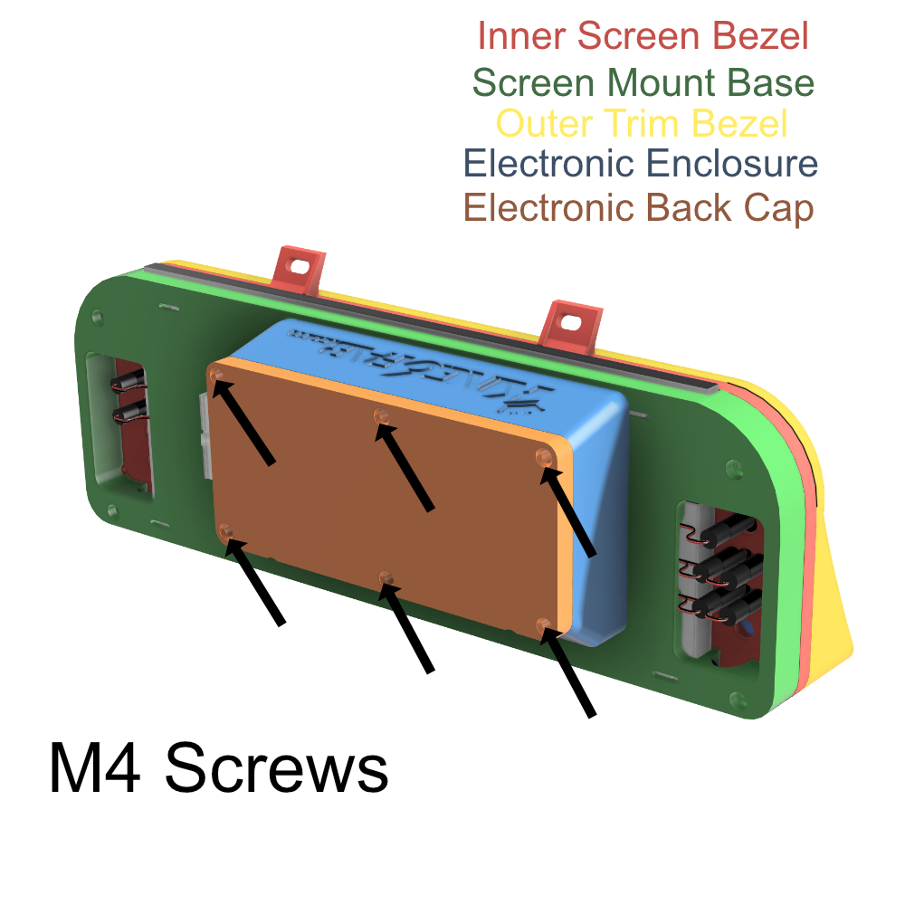
07. Dash Display Assembly Reference
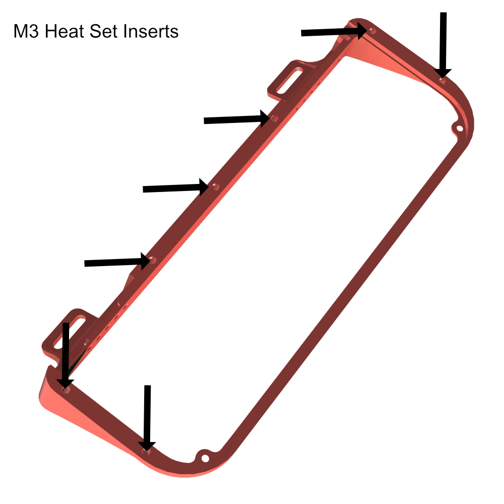
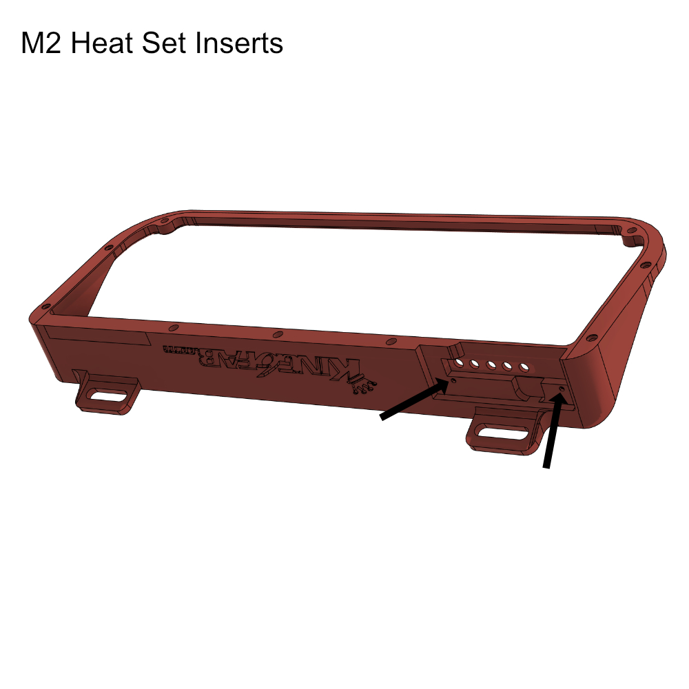
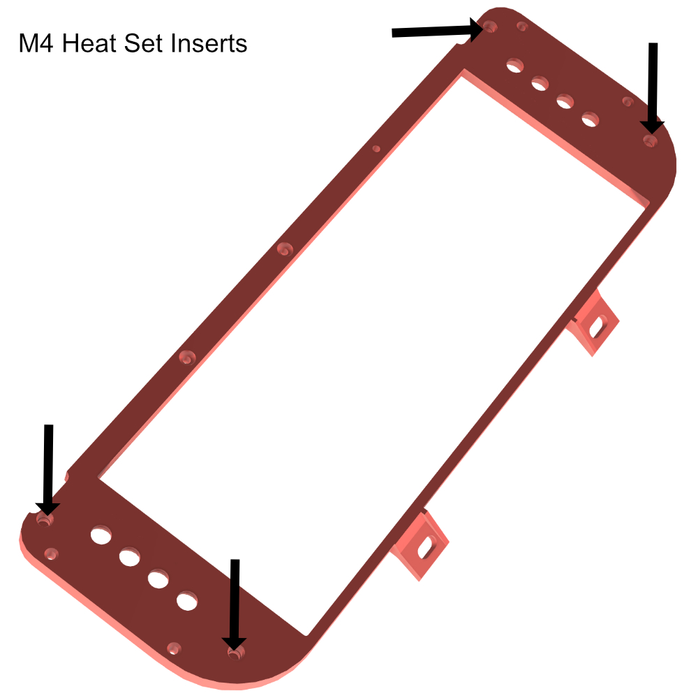
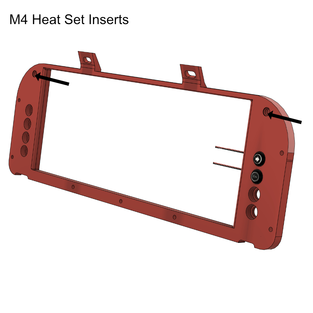
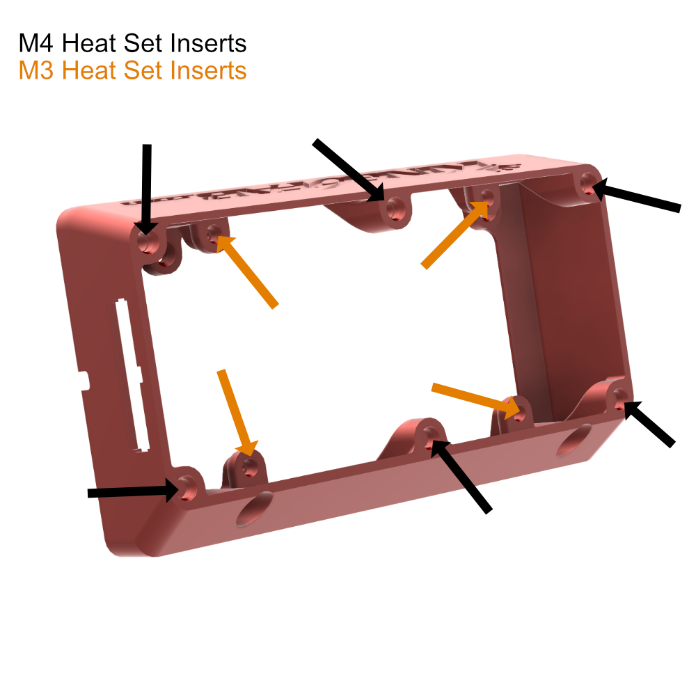
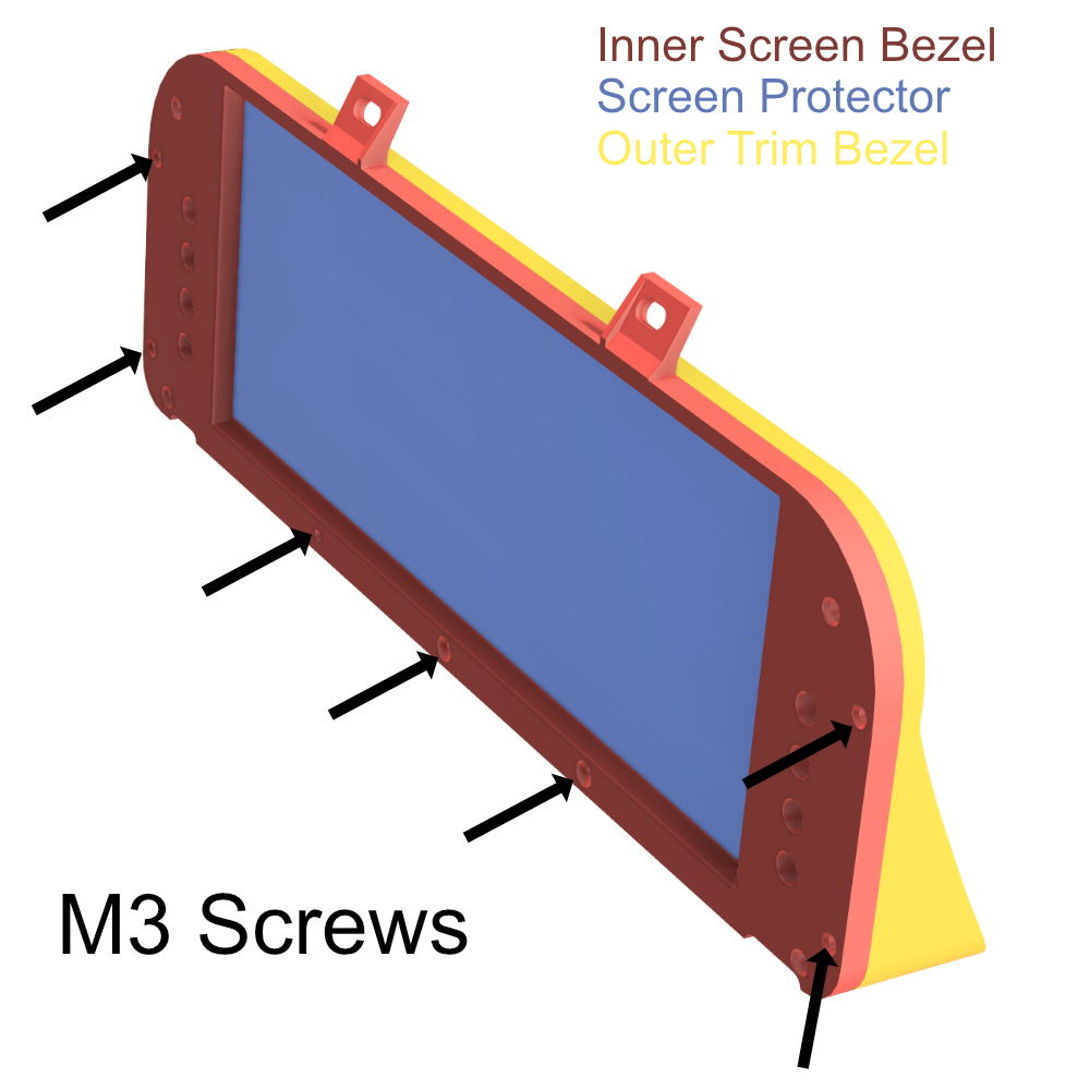
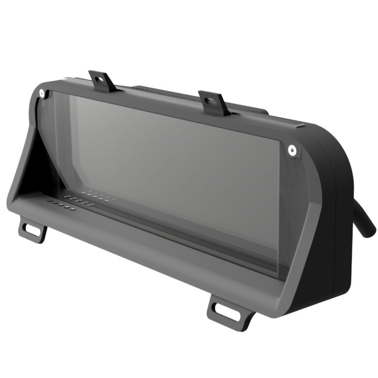
Outer Trim Bezel There are 4 Types of this bezel to choose from for 3D Printing: Screen Protector Bezel with Screen Buttons Screen Protector Bezel with Screen Buttons and Option Buttons…
1. Dash Display Purchase Guide
This guide is for referencing the various components/parts needed for purchase and how to wire them to the cluster.
All Links in this guide are non affiliate and are used as a reference only, Substitutions can be made at your discretion.
0. About The LCD Dash Display
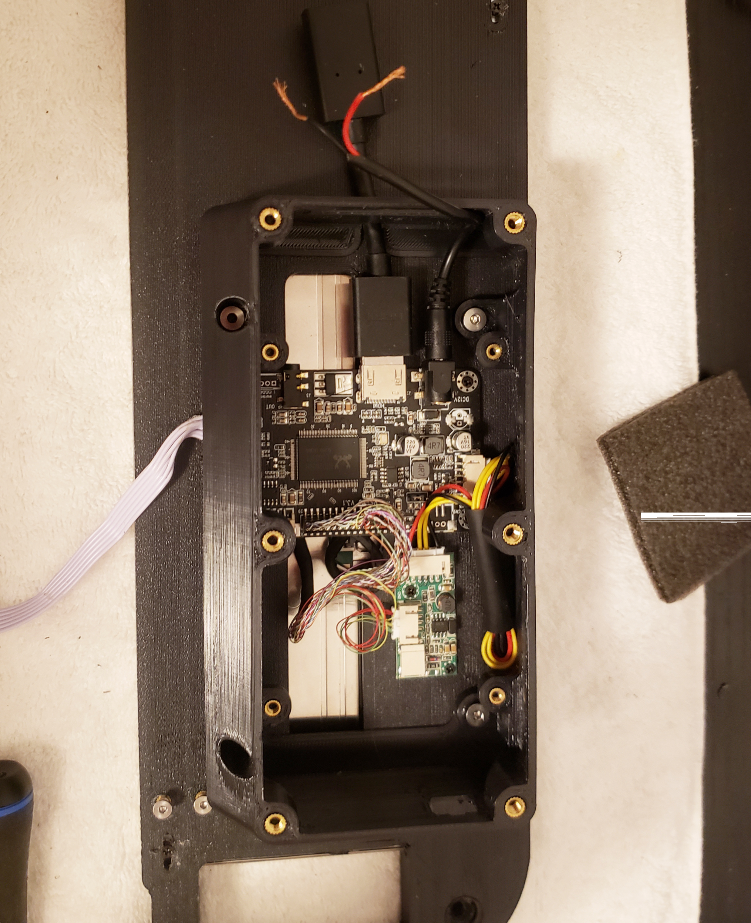
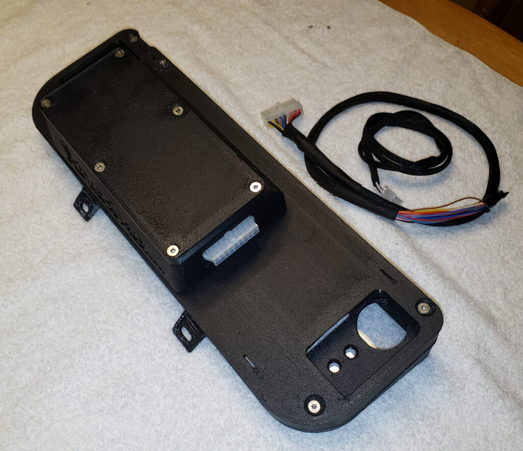
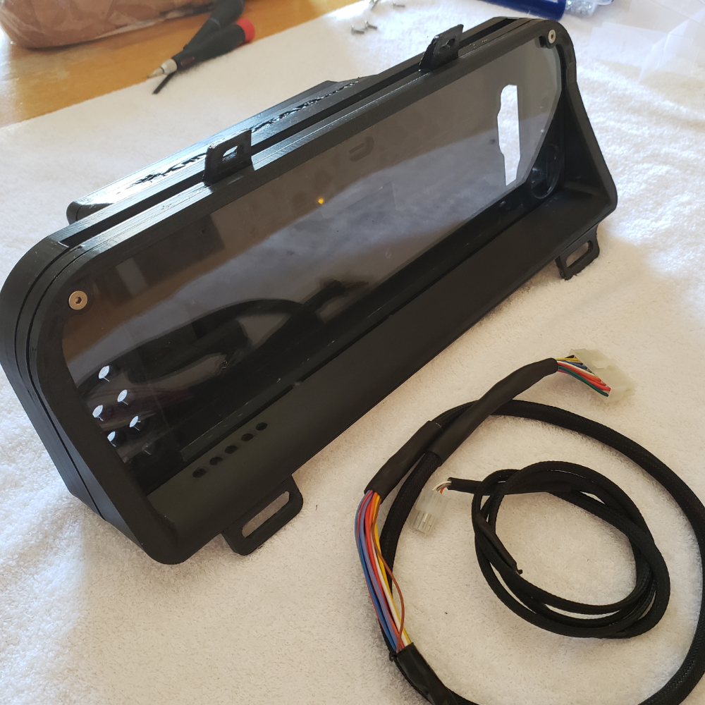
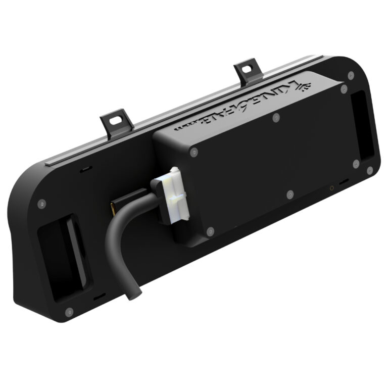
The King6fab dash display in the most basic explanation is an elegant way to hold a LCD screen with indicators in the factory gauge cluster position.
It was designed to look like it could have been a factory option, unlike other displays that look racer inspired with minimalist look often being affixed on top of a dashboard.
The dash display is simply a way to hold a LCD screen, it does not feature any software or tuning capabilities alone.
A way of thinking about it is, consider the dash display as comparable to a monitor you would buy for your desktop pc. Once you have the monitor you will need a device such as PC, Streaming stick, phone, gaming station, etc to display what you want on the monitor.
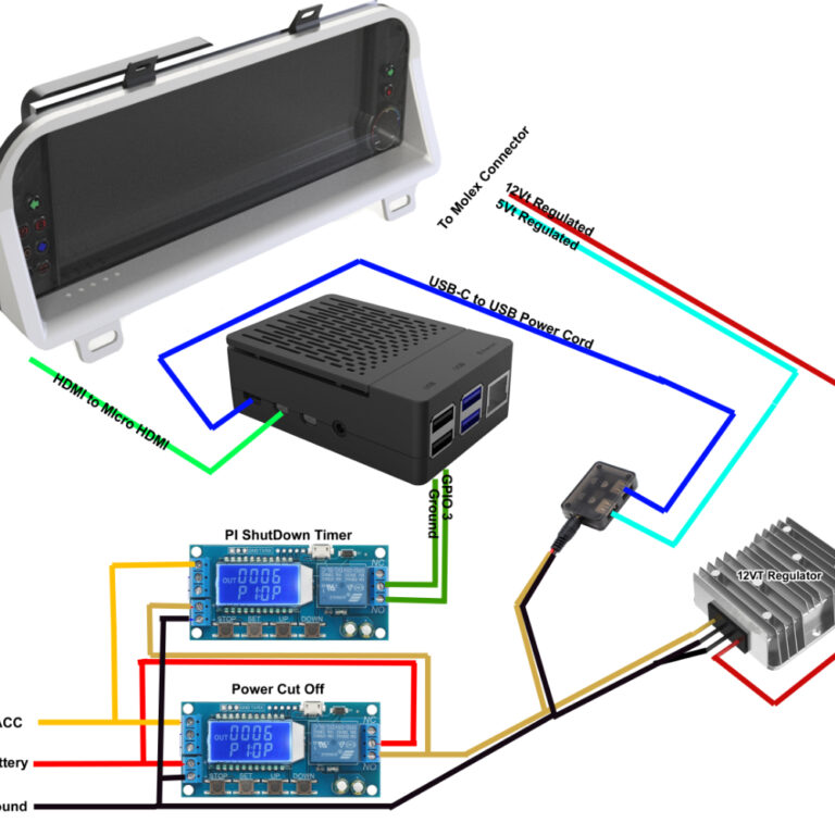
5.Dash Display Wiring Diagrams
Below is the pinout of the stock gauge cluster connectors by connector color and orientation. This information can be utilized for connecting external and software driven indicators. OEM Gauge Cluster Connector…
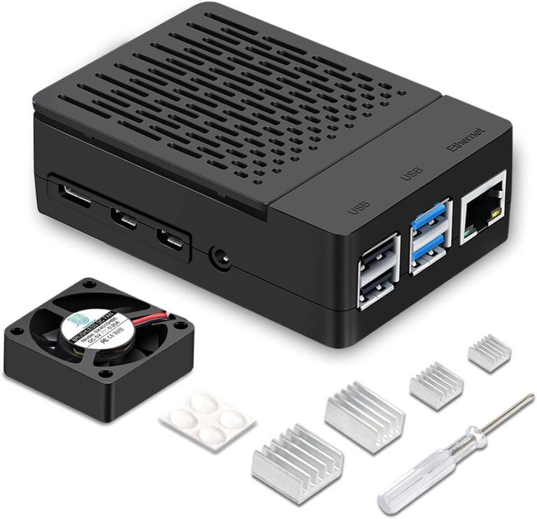
6.Recommended Display Device
Recommended Device to Use with LCD Dash Display 1. Device A. I have found the best all around device to use is a RaspberryPi 4B(4GB). With this device you will need…
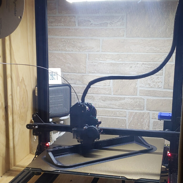
2. 3D Printing the Dash Display
How I printed the dash display: I used a Anycubic Chiron with PEI Texture plate. I modified the chiron with a BIQU direct drive print head. I then built a plywood enclosure around the printer and use a cheap office heater to heat the enclosure. This printer is normally very slow so I used software to increase its speed with the direct drives faster ability. This improves the print time by 60% but the machine is very loud.