
Similar Posts
Air Conditioning
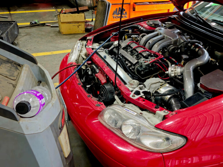
When I started building this car for boost in 2006 I decided it would be much easier to do without A/C. I removed every AC component in the engine bay and…
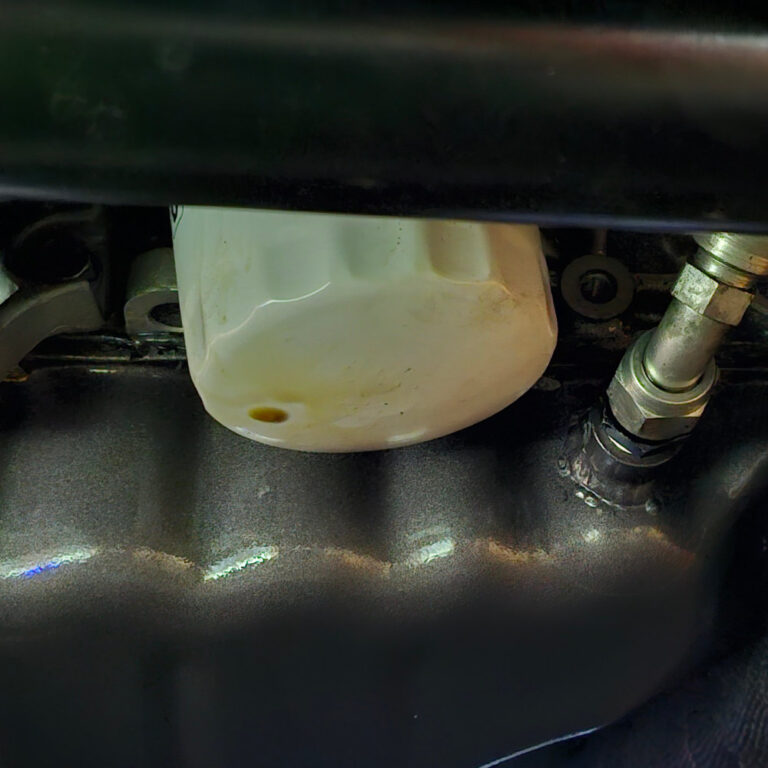
ZR1 Oil Filter Myth
The ZR1 oil filter has been long touted as an upgrade for the KLDE. I have used it since 2006 and ever since I have had a recurring problem, an oil…
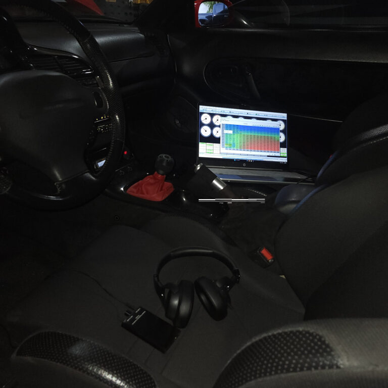
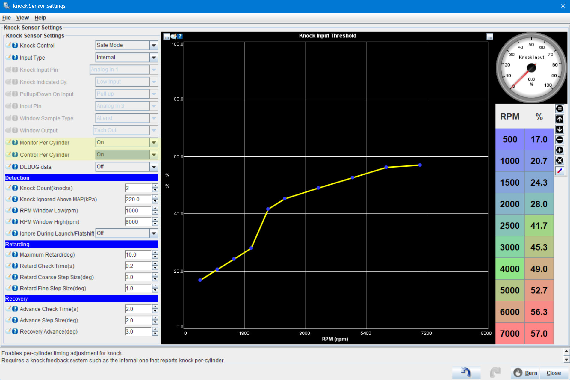
Knock Detection Tuning
For the past month I have been tuning the ignition table for my turbo Mx6. Particullary the locations under boost. This was important to do correctly to avoid engine damage. I…
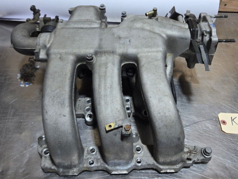
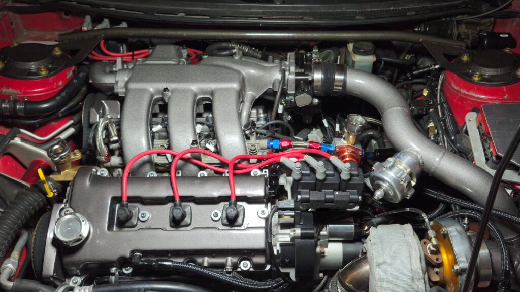
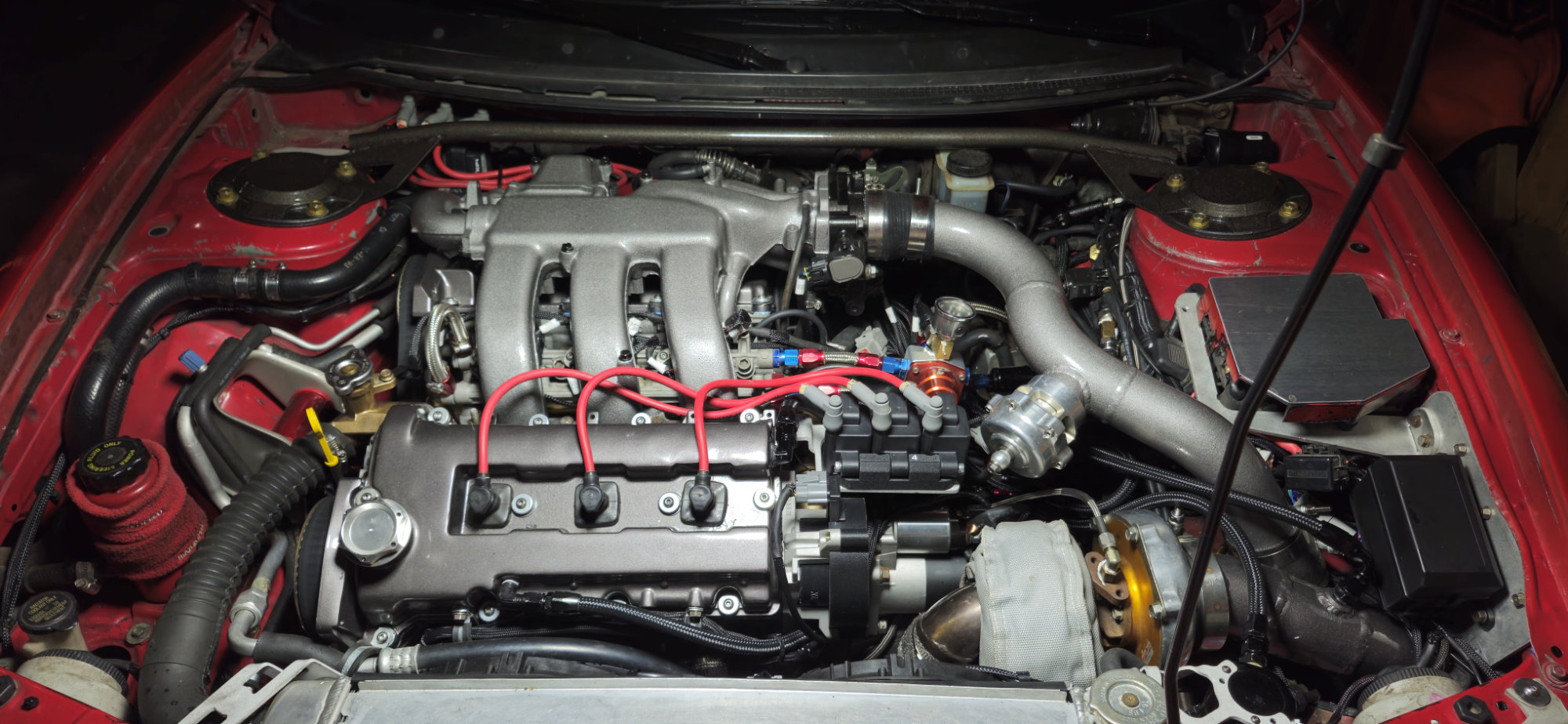
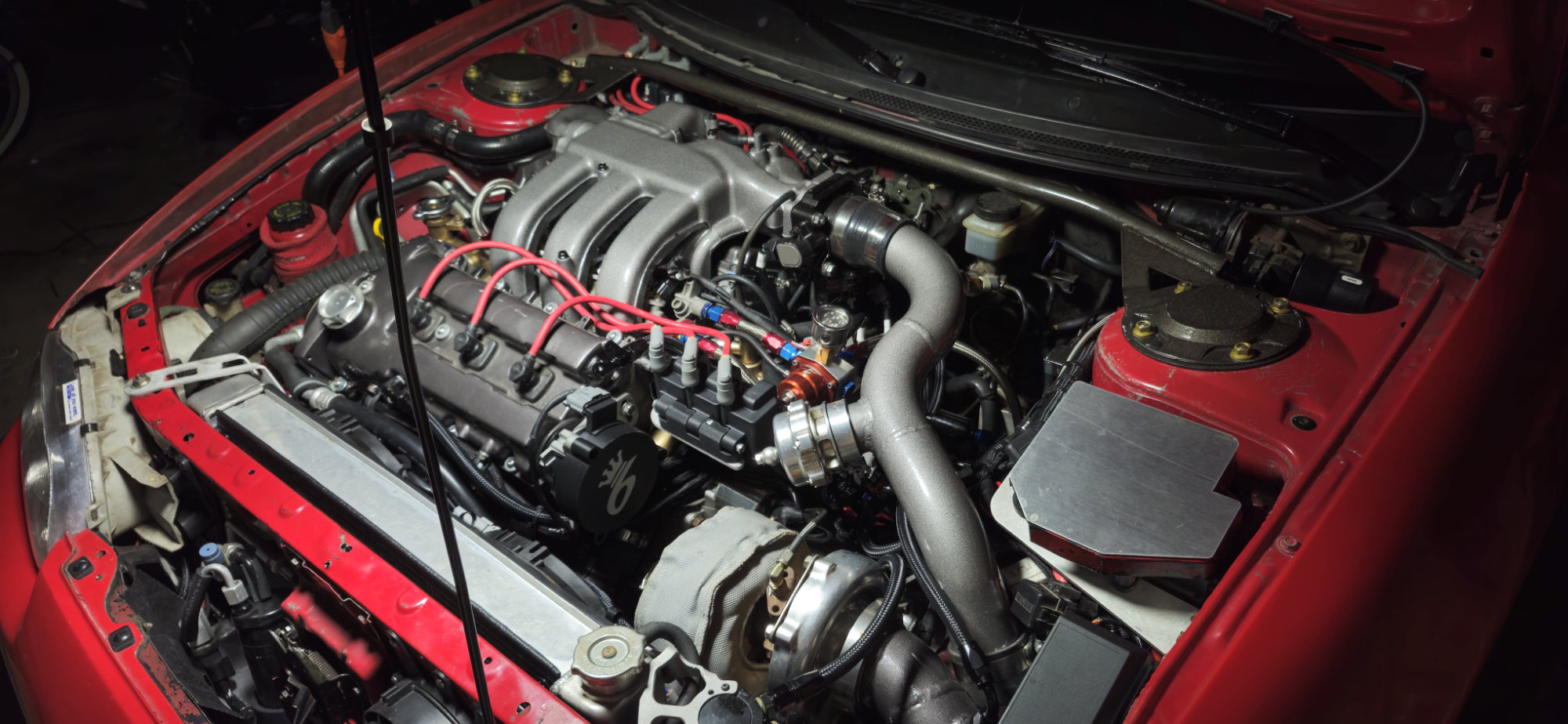
KLG4 Intake Manifold
I bought this intake manifold used off Ebay. The KLG4 is known to be a better intake manifold than the KLDE intake manifold and comparable to the KLZE Intake manifold
I did a lot of searching prior to buying this intake manifold particularly to see if a KLDE throttle body would fit on it. I have 2 KLDE throttle body’s already, why not make use of one and save my self some money.
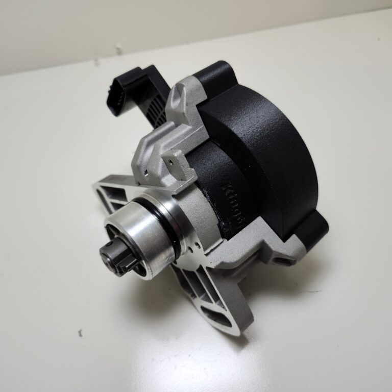
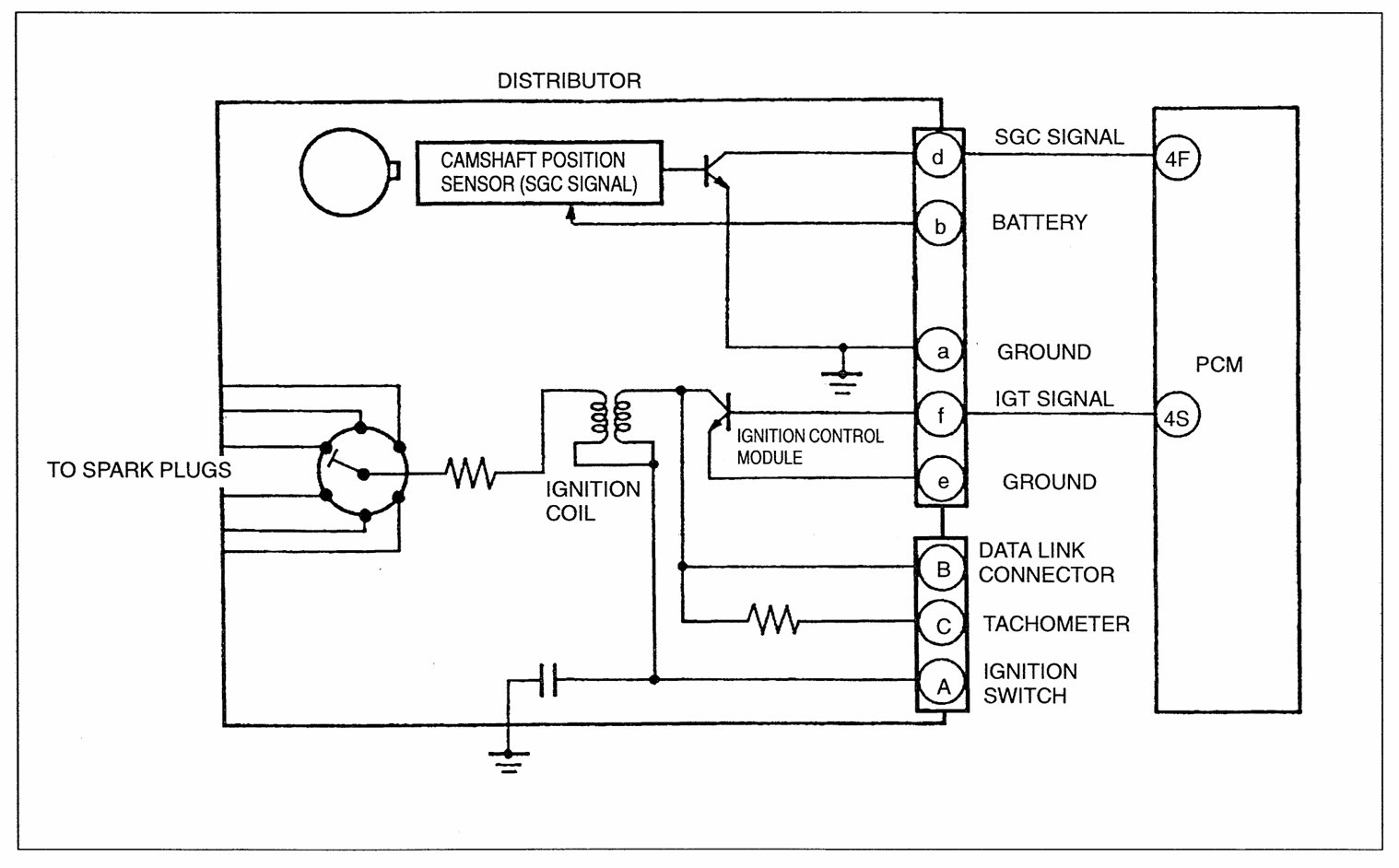
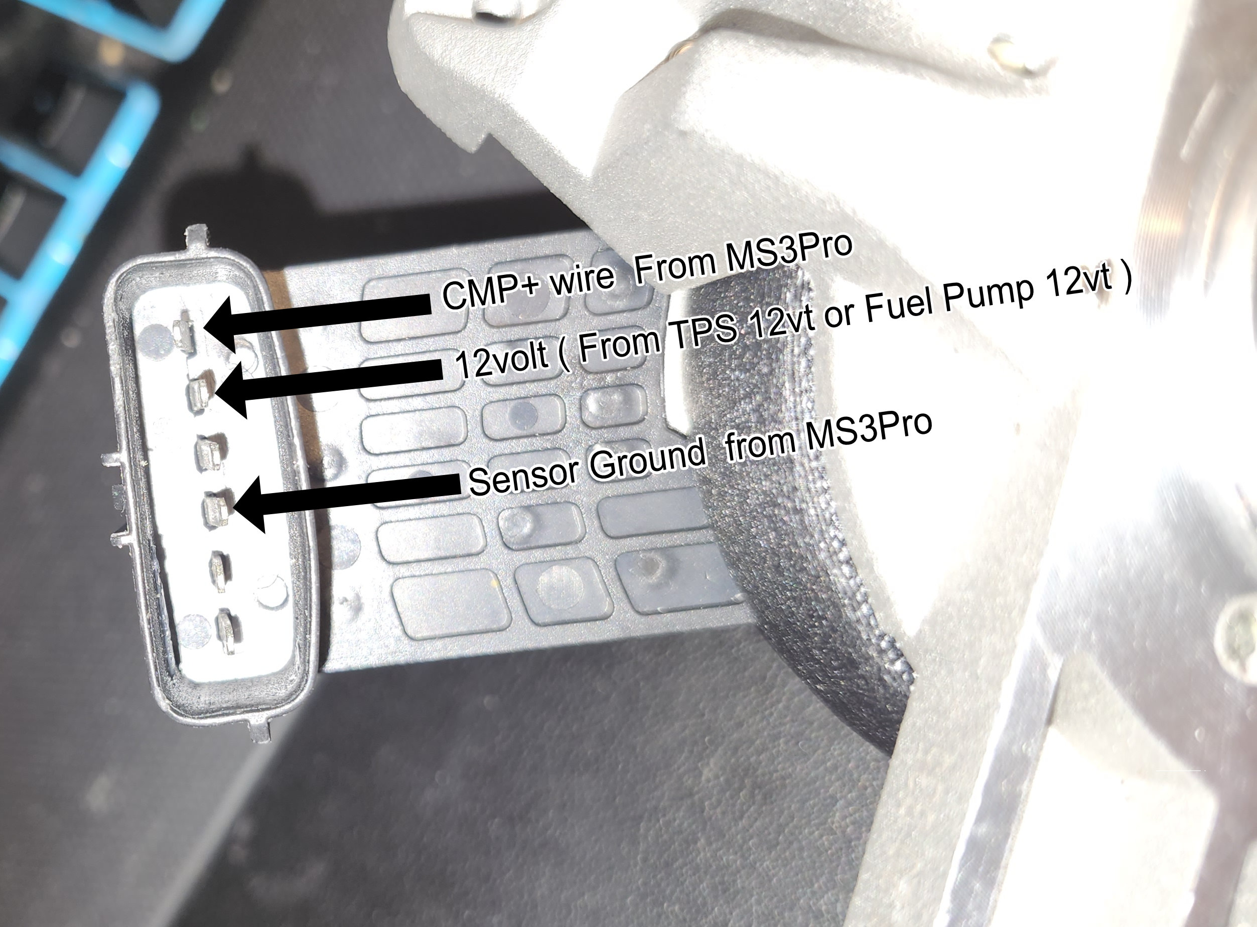
1995+ Cam Sensor Retrofit
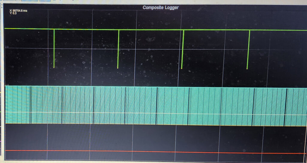
I have been planning on upgrading my standalone setup to sequential injection, to this the engine will need a cam sensor installed. There is various ways to do this, the cleanest…
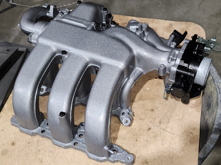
KLG4 Manifold Finishing
I had some plans for this manifold that changed last minute, for the better. I originally imagined this manifold painted in a wrinkle black color. But after doing a mockup photoshop…