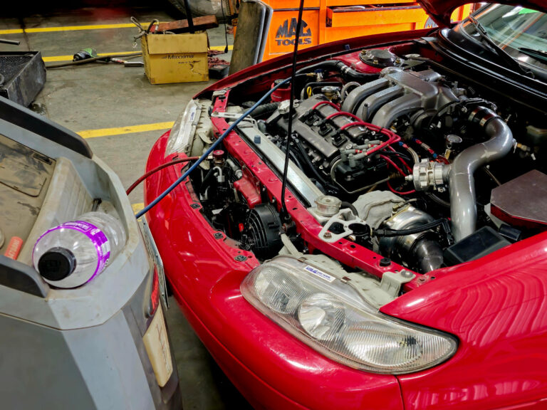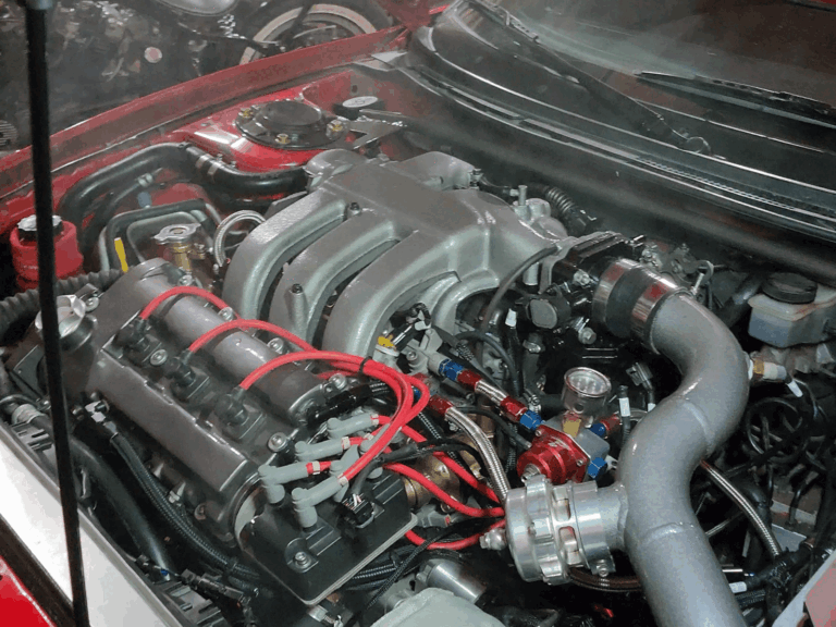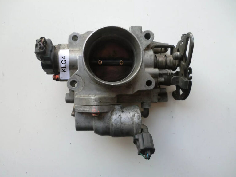
On my todo list has been the PCV system. I had previously used 6AN (3/8 ID) braided hose for all the connections, this included inlet from air filter and inlet to the intake manifold. All connections were spliced to each other and connected to the valve covers.
This simplify this explanation:
Front Valve Cover:
Air In at front of valve cover ( stock port location)
Vacuum out at top of valve cover ( stock port location)
Rear Valve Cover:
Air in at back of valve cover ( stock port location)
Vacuum out at back of valve cover ( custom location)
Both Air in’s connected to a Y fitting, witch route to a catch can, witch routed to the pre turbo pipe.
Both Vacuum out connect to a Y fitting, witch routed to catch can, with routed to a check valve, witch routed to the intake.
In theory this setup works and with low boost (under 10psi) it works good. However increasing boost to 15-20psi creates a lot of pressure in the crankcase that cannot escape fast enough out of the 6an hose for Air in.
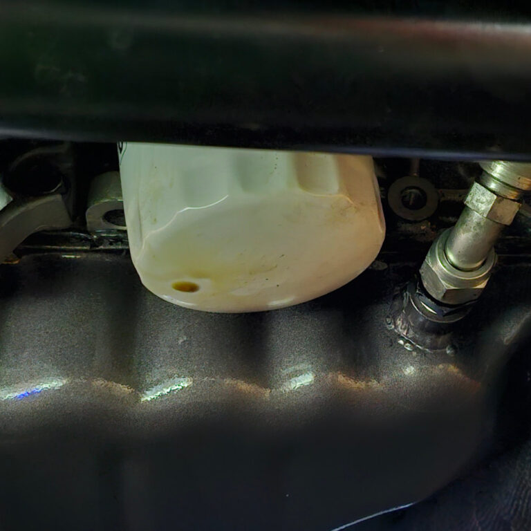
What happens is it starts pushing oil out hose, witch the catch can will acquire but this also puts pressure on the gaskets and seals in the engine. This caused oil seeping from the valve cover gaskets.
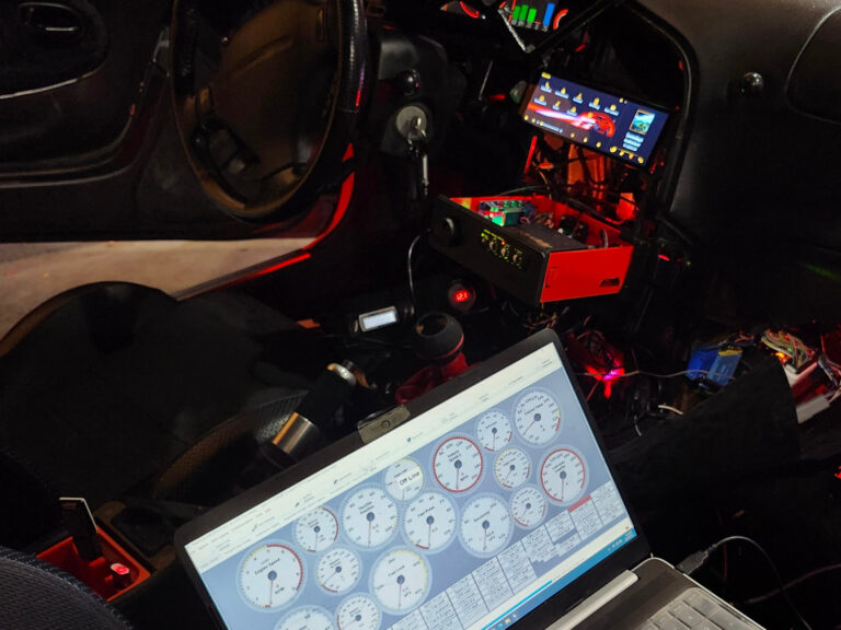
I installed a MAP sensor on the crankcase side of the PCV and documented the pressures, and its anywhere from 1-4psi of pressure depending on the boost.
The Plan:
Increase air in hose size.
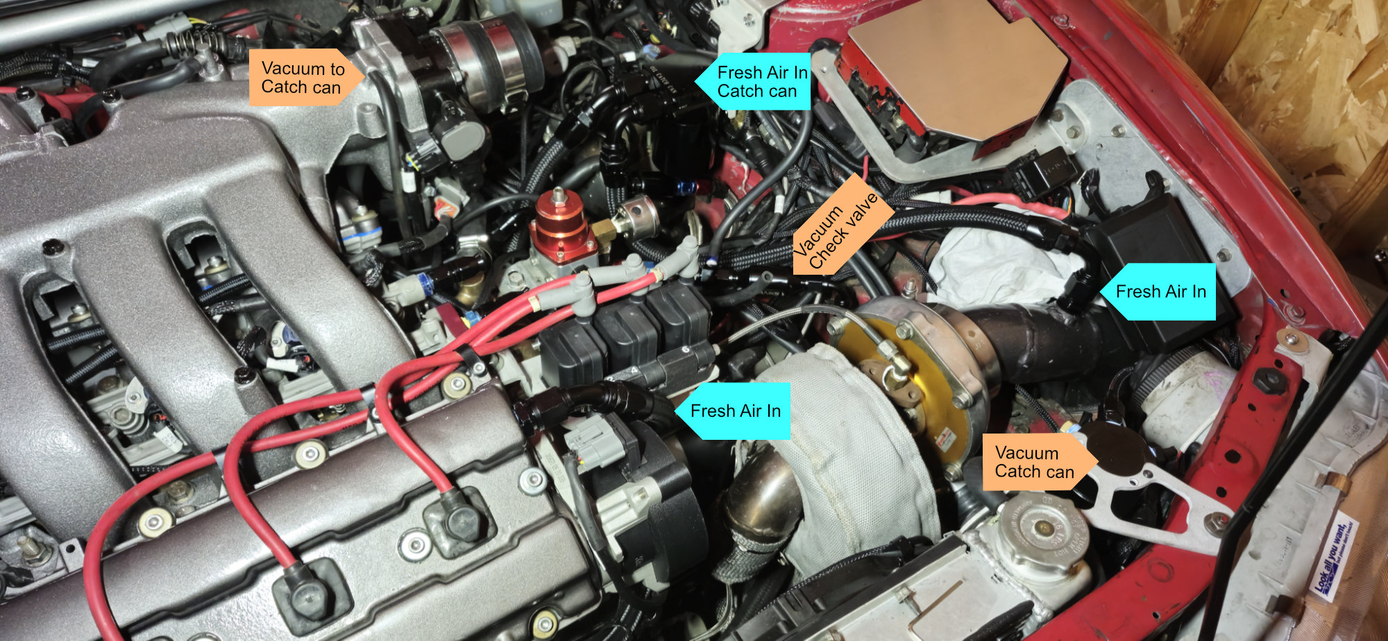
I chose to continue using the 6AN hose for the vacuum side of the PCV system, after all this part of the system is limited to the vacuum port size on the intake manifold.
I increased the air inlet side of the PCV system to 10AN, this is bordering the limit of what’s physically possible in this engine bay, 8AN possibly could have worked, anything larger then 10AN definitely would work but would be very difficult to fit.
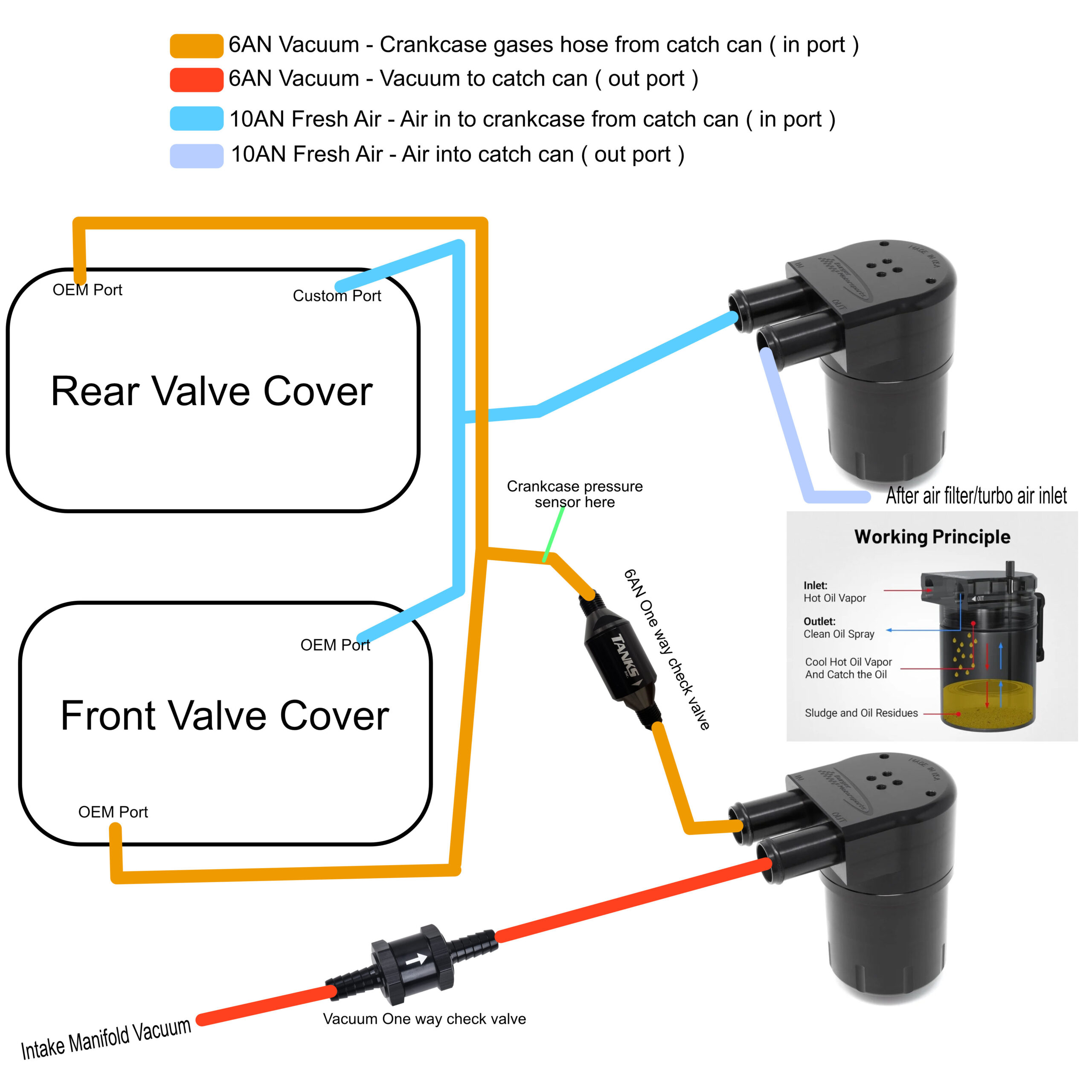
The shown diagram is how I routed my PCV system with each Valve cover having its own air in and vacuum out T’d together verses a system that has each bank dedicated to either vacuum or fresh air only. I figure this configuration ensures crankcase gases get fully remove from the engine vs either bank having gases trapped.
In my setup is a vacuum check valve to prevent boost from entering the crank case. I opted for a dual check valve system witch also allows me to monitor crank case pressure. The 6AN check valve ( a fuel type check valve ) in the location shown allows a map sensor to be installed before it witch is an accurate location for either boost entering the crankcase past the checkvalves or crankcase pressure.
How useful was this post?
Click on a star to rate it!
Average rating 0 / 5. Vote count: 0
No votes so far! Be the first to rate this post.
We are sorry that this post was not useful for you!
Let us improve this post!
Tell us how we can improve this post?