This How to has been Archived from clubprotege.com. All Credit goes to the author. To see original website Click Here for wayback machine archive.
Installing a HEI Ignition Module on MX-3
with or without External Ignition Coil
by Wil Fellows (Gro Harlem) 10/10/2004
Applications:
92-94 MX-3 GS
93-94 Ford Probe GT
93-94 Mazda MX-6 LS
93-94 Mazda 626 ES
Estimated Time: 2.5 hours
Tools / Supplies you will need:
Basic wire-stripper / Crimping tool
Ratchet or wrenchset (12mm needed to remove distributor, 10mm may be needed to remove bolts to secure bracketry)
Wire loom
Electrical tape
Solder & Soldering Iron (if you don’t want to use crimp terminals)
Pliers (to bend bracketry)
Cutters (to cut bracketry)
OPTIONAL (If installing an external coil as well):
Dremel tool with grinding bit
Overview of Parts you will need:
HEI 4-pin Ignition Module (to find this, go to the first step in the install instructions below)
20 or so feet of 16-gauge wire
Peice of perforated steel bracketry
A couple of small bolts w/nuts or screws w/locking washers.
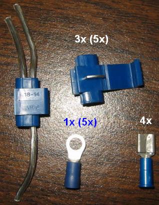
Four BLUE female disconnect terminals
Three BLUE self-tapping terminals (also called “Insulation Displacement Connectors or IDC for short)
One BLUE Ring terminal
First of all, I’d like to thank the awesome ProbeTalk community for their extensive discussion on this topic, particularly Joe Bialy for founding this information. For more info go here.
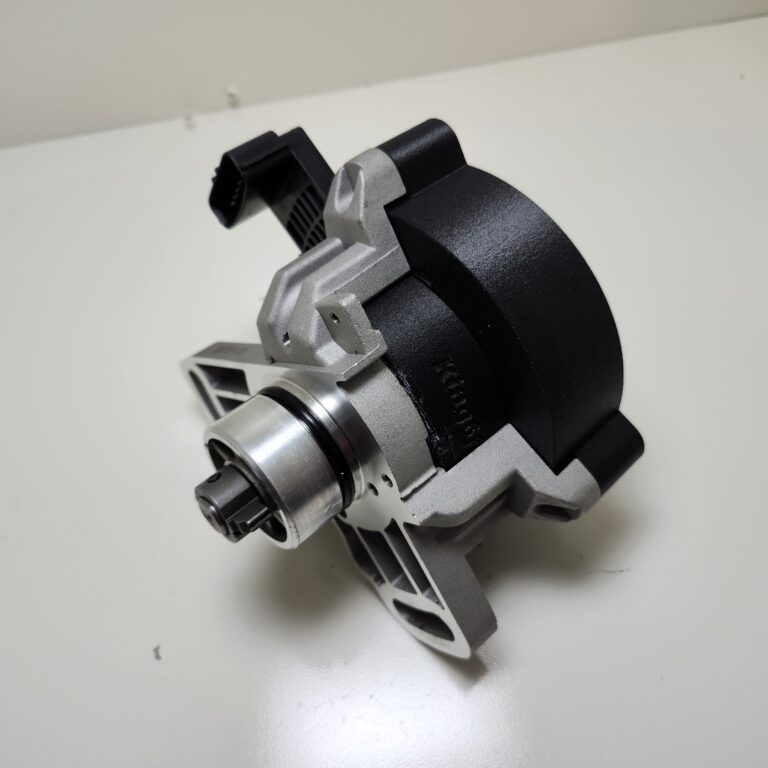
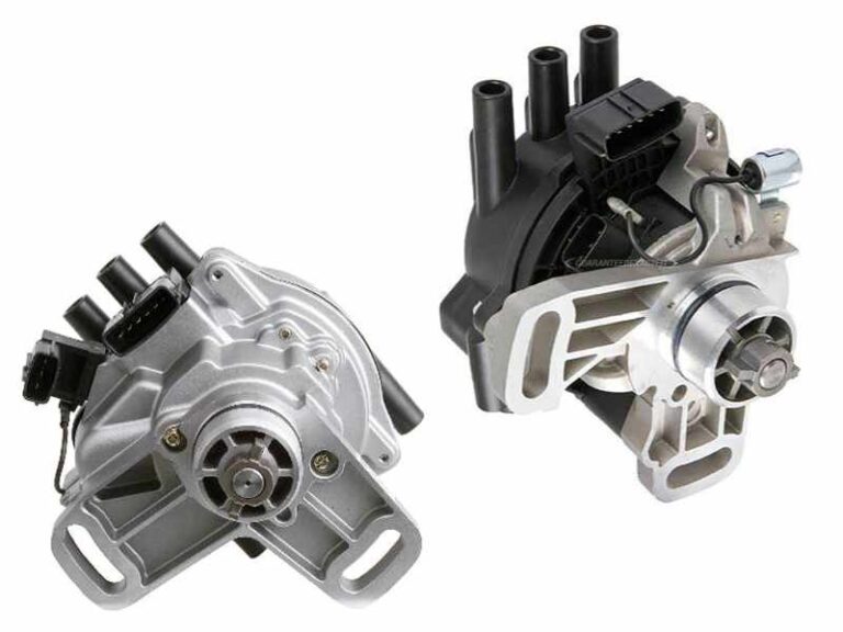
This how-to outlines how to install a GM HEI ignition module in place of your stock distributor Ignition module. As you may or may not know, the stock internal-coil distributor on the MX-3 is very failure prone, this is almost always caused by a faulty ignition module.
How Do I know my ignition module is bad?
For starters…if you are driving and your car suddenly cuts out, you wait and a few minutes later it starts back up, it is most likely the igntion module. If you aren’t so lucky, you will be stranded & require a tow (i’ve been stranded twice in the past thanks the the POS stock module). If your module does blow out, your only real option is to buy a new or remanufactured distributor which costs at least $150 and that doesnt’ even guarentee you won’t get stranded in the future (i’m on my 4th distributor in just over a year of driving my KLZE mx3)
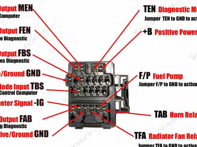
If you pull the OBD-I code from your ECU after an ignitor failure, you should get the “cam angle sensor” code
What can I expect after performing this mod?
Well for one, your car will be more reliable (assuming you don’t do a halfassed job of wiring it all). You won’t have to worry about your car randomly breaking down on you. You will also notice the starting improve if you’ve had problems in the past where you have to crank it 3-5 times before it starts on a cold morning.
I personally feel a more consistent power curve when flooring it in 2nd or 3rd gear, my engine doesn’t stutter like it used to. I’m not going to get people excited and say I felt a power difference, but the fact it pulls more consistent DOES feel to me like it pulls harder, but it might all be in my head.
This module apparently puts out as strong a spark as a MSD 6AL ignition control box, but uses less current (a max of 5amps instead of a constant 10 that the MSD requires).
Approximate Cost Overview:
- HEI Module (aftermarket, new): $17-22 plus tax
- Female Disconnect 6x pack: $1.99 plus tax
- Ring Terminal 6x pack: $1.99 plus tax
- Self-Tapping terminal 4x pack: $1.99 plus tax
- 25-feet of 16awg car wire: $2.99 plus tax
- 5 foot long perforated steel bracketry: $4.19 plus tax at lowes
- Nuts/Bolts/Screws to secure HEI to brackrtry: $2-4
Total Approximate Cost: 32.16-39.16
Add an External Coil:
- MSD Blaster 2 Coil or equivalent: $28.95 plus shipping
- Coil Bracket (summit racing brand): $2.95 plus shipping
- MSD 8.5mm Coil Wire: $8.95 plus shipping
- MSD Power Tower (should come with coil wire): free!
- High-temperature RTV Silicone tube: $2.99 plus tax
- Additional Self-tapping terminal pack: $1.99 plus tax
- Any additional wiring, nuts/bolts/screws or terminals: ~$2-4
Total Additional Cost (approx): $47.88-49.88
OPTIONAL parts required(if installing an external coil as well):
- External Ignition coil…aftermarket or OEM (your choice)
- Mounting bracket for Ignition coil
- More bracketry & nuts & bolts to secure ignition coil
- 12″ ignition coil wire
- an MSD “Power Tower” for your distributor cap
- (OPTIONAL) If you dont’ want to drill into your distributor cap, you can buy a pre-modded cap from ProbeSport click here
- Some high-temperature RTV silicone sealant/gasket maker
- 4 additional BLUE terminals to secure to MSD power. I used 4 ring terminals.
- A 1000-ohm resistor 1/2 watt.
- Maybe 5 feet additional wire 16-20gauge
Information to know about before attempting this conversion:
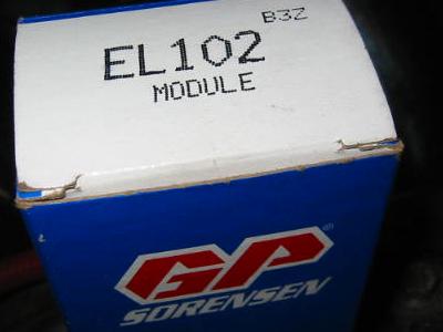
HEI Modules, where to get them:
I bought my module for $17.99 at Advance Auto Parts. I told them I needed it for a 1982 Chevrolet Chevetter 1.6 liter and I got the GP Sorenson (hong-kong-based company that advance auto only seems to carry) part number EL 102. At Autozone the part costs the same but is made by Wells and is part number DR-100. You can also get this used from any early-late 80’s GM car. Basically ALL GM’s from this time period use this same module from 4-bangers to V8’s. Apparently the module is mounted inside of the distributor cap on these cars and shouldn’t cost more than $5 if your junkyard is reasonable.
Crimp Terminals? Or Solder?:
Many people believe crimp terminals to be unreliable and only used by amatuers. I’ve wired dozens of stereo’s for people in the past, and I have yet to hear of a single failure from any of my friends on my wiring. If you crimp the terminals FIRMLY and TEST them by tugging both ends for any signs of coming apart, you won’t have any problems with them falling off or shorting your stereo (or in this case, ignition) out. The way I see it, Solder is dead-reliable and less expensive, but can be messy & requires skill. Dripping solder on your engine parts isn’t a good thing. Crimp-terminals when used properly can prove reliable & are very easy to use but cost money (not much) and look ugly due to their multiple color scheme. For this HEI install, you’ll just need the 14-18 guage BLUE colored terminals.
Using electrical tape to connect wires is flat out red-neck and WILL CAUSE A FAILURE eventually. I don’t care how good you are with elec tape…the stuff will heat up and the glue will cause it to unravel inside the engine bay within a couple of trips on the road.
Self-Tapping (IDC) Terminal Info:
At the top of this page under “what parts you need” I put a picture of a self tapping terminal before it is used & after. Most people are unfamiliar with these things, but they are quite handy. They let you tap into a wire without cutting it…they simply push the metal clip down into the wire & the new wire you shove into the second end also gets connectivity through this metal clip. (See picture)
Wire Info:
It is IMPORTANT to use at least 16-gauge wire for the “G” pin on the HEI module to the ECU trigger output wire (orange on mx3). This wire has up to 5-amps running through it. Using 16-18AWG will work fine for the rest of the wire connections.
Also….use car wire. Speaker wire uses very soft plastic shells that will melt if they contact any engine parts. You can try using it, but be warned that it might fail after awhile. Car-specific wire has harder sheaths and is very inexpensive. Use wire loom to clean up the installation instead of having a million random wires running throughout the engine bay that look like shit.
Before I talk about the wiring, I’ll discuss the IMPORTANT parts of installing this device so it works RELIABLY. I’m applying my knowledge based on what I’ve read on ProbeTalk and my own experience installing this thing.
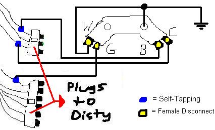
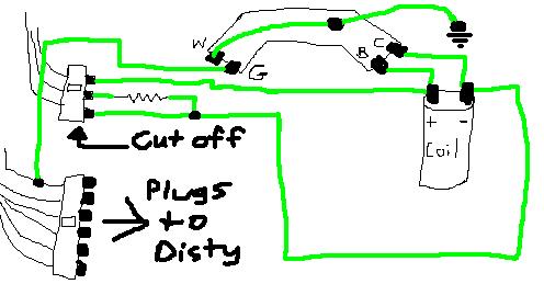
The above diagrm outlines the wiring of the HEI module. You Must ground pin W as well as the right-most screwhole. Grounding the entire backing plate will result in a much cooler operation of the module.
Using the self-tapping terminals wire the remainder of the module to your stock ignition harness (you do not need to cut any part of the harness if you use self-tapping terminals).
-Wire the top-most wire on the 3-wire distributor plug (solid blue in color) to the “B” terminal on the HEI module
-Wire the bottom-most wire on the 3-wire distributor plug (solid red in color) to the “C” terminal on the HEI module
-Wire the top-most wire on the 6-wire distributor plug (solid orange in color) to the “G” terminal on the HEI module
Now for the Installation Instructions:
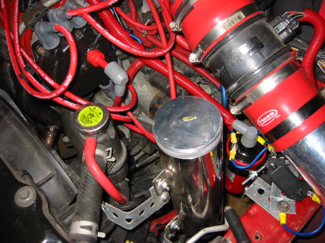
1: Before you start wiring everything together, you should determine where you are going to mount your external ignition coil (if applicable) and HEI module. I chose to locate both along the passenger-side fenderwell because there were two threaded bolt holes and nothing in the way since I previously installed a custom cold-air intake.
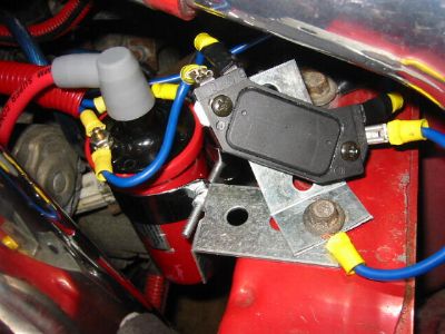
For MX-3 guys, these two bolt locations are perfect for a Ignition Coil. The top one in the pic is a 12mm while the closest one is a 10mm bolt. I used the 10mm to also secure the HEI module as seen in the pic to the lower-right.


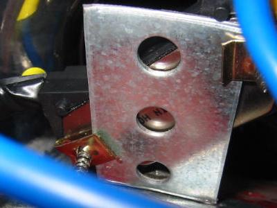
2: MAKE SURE you create a bracket for the HEI module or your module will heat up significantly, which can lead to its failure. To be safe, create a custom bracket out of some 1″ wide (or wider) bracketry and secure the HEI to it so that the bottom of the HEI (the part that is metal) FLATLY sits on top of it. This will ensure the HEI module is grounded well and working properly. It will also run at a much cooler temperature.
As you can see in this pic, I grounded the back of hte HEI flat-against the bracket I made for it. I secure it with some car stereo screws w/retainer clips that I had in my toolbox.
IF YOU ARE INSTALLING AN EXTERNAL COIL, SKIP STEP 3 and go to step 4.
3: Once you have figured out where to mount all the stuff, you can begin wiring it all together into your distributor. See the diagram below:

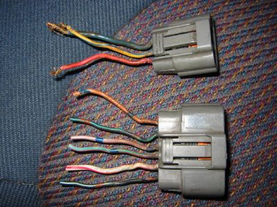
For Informations Sake, below is a list of the MX-3 Distributor plug wire colors & their functionality:
6-pin Plug (from the top to bottom)
Solid Orange (Ignition control module ecu trigger)
Black w/green stripe
Pink w/white stripe (camshaft position sensor SGC signal)
Pink w/green stripe (camshaft position sensor SGT signal)
White w/red stripe
Black w/light-green stripe (ECU constant ground)
3-ping Plug (fromp top to bottom):
Solid Blue (ignition coil +)
Yellow w/blue stripe (tachometer signal from ignition coil)
Solid Red (ignition coil -)
3 (Explained): To hook up the HEI module so it functions properly you will need four wires, each with a female disconnect on one end and one with a ring terminal on the other end and the other 3 with the self-tapping terminals.
- The wire with the ring terminal is used on pin “W” on the HEI module and is grounded to the chassis of the car
- One of the three other wires is routed to the top (solid orange) 3-pin Plug from the distributor and connects to pin “B” on the HEI module
- The 2nd of the three other wires connects to the bottom (solid red) wire on the 3-pin Plug from the distributor and connects to pin “C” on the HEI module
- The last wire MUST BE at least 16-guage and connects to the top wire on the 6-pin distributor plug (solid orange) and connects to pin “G” on the HEI module.
You are DONE! Your car should start up. If it doesn’t…make sure your connections are good. Also check to see if the HEI module is getting very hot, if it is, you will need to ground it better and/or use larger gauge wire for the “G” to Orange wire.
If you are installing an external ignition coil as well, continue forward, if you are not, IGNORE ALL OF THE FOLLOWING STEPS.
Before you can wire up everything to the ignition coil and HEI terminal, you will need to prepare your distributor and distributor cap for the external coil.
If you don’t think you can successfully rig your distributor cap to accept an external coil wire you can buy a pre-modified (and prettier) distributor cap from ProbeSport for about $60 shipped. CLICK HERE.
4: First you will need to install the “MSD Power Tower” into your distributor cap. Doing this will bypass the stock ignition coil and will route the spark to the power tower terminal so you can connect the ignition coil wire from the outside of the cap to the ignition coil.
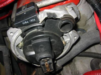
There are many ways to do this, I chose to rig my power tower near the middle of the cap. I used a drillbit to drill through the plastic cap & metal and I used the screw from the powertower to secure it. I made sure the hole was deep enough so the screw was recessed inward, so I had enough room to fill in the remainder with high-temp RTV silicone gasket maker. The red “power tower” sticks out of the top of my distributor cap and I sealed around it with more high-temp RTV silicone gasket maker. I also cut off the old post sticking out of the lower-left of the cap (see pic to the bottom-left) so the stock coil wouldn’t interfere with the new coils spark. I put a glob of sealant over it so it wouldn’t cause any shorts.
The modified cap is seen below.


5-A: Now you will need to prepare your distributor for the use of an external coil. Since the stock distributor has a built-in ignition coil, you do not need it. If you want to, you can remove it and save yourself a couple of pounds of unnecessary weight and to prevent the stock coil from interfering with the new external coil.
Removing the stock coil isn’t too hard, you have to remove all of the screws holding all of the distributor guts in place and then you will see the coil with the 3-pin plug sticking out of it. Remove all of that and seal the remaining hole with some of the high-temp RTV silicone
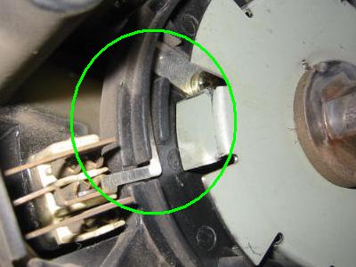
5-B: If you do not want to remove your stock ignition coil, you will have to disable the coil by removing the strap going from the distributor brain to the tachometer signal from the coil. You can either cut it off or unscrew it and slab some silicone over it so it won’t contact any of the metal parts. The pic to the right shows what strap I am speaking of
6: Now you can wire the stuff together. First, install the distributor, cap and rotor and wire it according to the diagram below:
For Informations Sake, below is a list of the MX-3 Distributor plug wire colors & their functionality:
6-pin Plug (from the top to bottom)
Solid Orange (Ignition control module ecu trigger)
Black w/green stripe
Pink w/white stripe (camshaft position sensor SGC signal)
Pink w/green stripe (camshaft position sensor SGT signal)
White w/red stripe
Black w/light-green stripe (ECU constant ground)
3-ping Plug (fromp top to bottom):
Solid Blue (ignition coil +)
Yellow w/blue stripe (tachometer signal from ignition coil)
Solid Red (ignition coil -)
6 (Explained): To hook up the HEI module so it functions properly you will need seven wires total.
1: One of the wires with a ring terminal is used on pin “W” on the HEI module and is grounded to the chassis of the car
2: Another wire goes from the “G” terminal on the HEI module to a self-tapping terminal on the orange wire (top wire on the 6-pin distributor plug). This wire MUST be at lesat 16-gauge or the HEI module may get extremely hot and/or the wire will melt due to the 5-amp current this wire requires.
Wires 3-6 can be connected two ways, you can either run all of the wires off of the “B” and “C” terminals from the HEI module OR (as shown in my diagram) run all of the wires off of the “+” and “-” inputs from the external ignition coil.
3: The next wire depends on which way you run your wires. This wire needs to go from the ignition coil’s “+” to the HEI “B” pin.
4: Another wire needs to go from the coil’s + pin (OR hei “B” pin) to the top wire on the 3-pin distributor plug wire (solid blue).
5: Now you need a wire going from the “-” input on the external coil to the HEI “C” pin.
6: Then, you need a wire from the coil’s – pin (OR hei “C” pin) to be routed to the 3-pin distributor plug’s bottom wire (solid red).
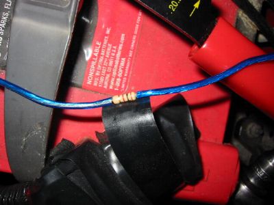
7: Lastly, you’ll need to rig the tachometer to work. In order to do this, use a self-tapping terminal on the #6 wire you just hooked up. Cut this new wire in half and shove a 1000-ohm resistor inside of it. I TIGHTLY wrapped electrical tape over the resistor and two-wires that the resitor is shoved in so it won’t fall out. If you do it this way, use wire loom to cover the electrical tape and sheild it from too much heat. (see picture to right to see how I did mine)
NOTE: USE A RESISTOR for the tach signal, if you do not, you will burn out your tachometer in no time. The stock ignition coil has a 1k-ohm resistor built in for this purpose.
7: Now you can connect the ignition coil wire to the distributor cap, wrap everything up with wire loom to clean up the install & tighten any bolts that may be loose.
Turn your key, and your car should start right up! If it doesn’t, check your connections and wiring for accuracy or a loose connection. Also check to see if the back of the HEI module is HOT. If it is, you’ll have to ground it better and/or increase the size of the “G” to orange wire so it gets sufficient current.
Copyright © 2004 ProjectMazda.com. All rights reserved.
How useful was this post?
Click on a star to rate it!
Average rating 0 / 5. Vote count: 0
No votes so far! Be the first to rate this post.
We are sorry that this post was not useful for you!
Let us improve this post!
Tell us how we can improve this post?