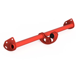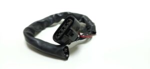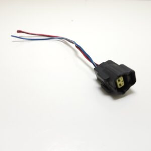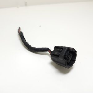
Warning! Do not route these harness’s over hot objects such as exhaust manifolds or piping
Begin your install at Step 10 of DIY Autotune’s PNPMS install instructions:
Quoted: “The MAP sensor vacuum hose will pass through the large rubber grommet that the factory wiring harness passes through the fire wall. There is an area just to the right of the factory harness that, using your sharp punch/awl or small screwdriver, you can easily poke a hole through to pass the MAP sensor vacuum hose through. Optionally, install the included threaded bulk head fitting into the hole you just made in the grommet. This will prevent the hose from possibly becoming pinched within the grommet. Otherwise, simply pass the hose through the grommet into the engine bay.”[/vc_column_text][vc_single_image image=”1145″ alignment=”center” onclick=”img_link_large”][/vc_column_inner][/vc_row_inner][vc_row_inner][vc_column_inner][vc_single_image image=”3346″][vc_column_text]Make an extra hole in the rubber grommet to push harness 1 thru, wrap tape around the bare wire ends to form a point and push the harness thru the grommet from the engine side, Pull enough harness thru to route to the front of the PNPMS unit.
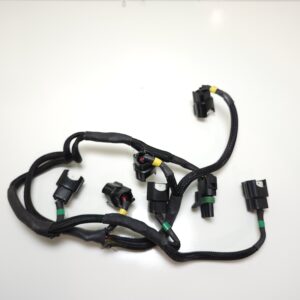
Harness 1 (Thin with Orange,Yellow & Green wires)
Connect Harness 1 to the Quad Spark Inputs, the harness is color coded yellow, orange, green, these will go the same colored wires at the Quadspark using crimp connectors with shrinkable ends.
Note: The remaining blue wire from the quad spark will remain unconnected, this remaining wire is a 4th igniter inside that is unused for the V6.
Connect the opposite end of harness 1 to the DB connector for your MSPNP, the wires are designated by color. Use the below reference for your version of MSPNP.
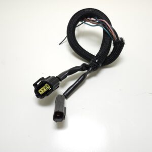
Harness 2 (largest harness with coil pack connector)
Connect Harness 2 to the Quad spark, the harness is color coded labeled with White, Pink, Green, these will go the same color coded wires at the quadspark using the crimp connectors with shrinkable ends.
Note: The remaining purple wire from the quad spark will remain unconnected, this remaining wire is a 4th igniter inside that is unused for the V6.
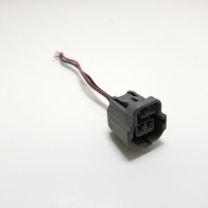
Connect the opposite end of the harness to the coil pack,
A short section of wiring splits off harness 2 that has a built in tachometer adapter, Do not bend this area as you could damage the diodes inside.
Power & Tachometer
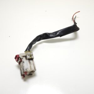
The end of this tach adapter harness will be wired into the 3pin connector normally plugged into the distributor, You will need to cut the 3 pin distributor connector off the OEM harness, if you plan to ever go back to the OEM/Distributor ignition, make sure you cut far back behind the connector so that the connector can be wired back on.
Power:
The blue wire on the harness will get connected to the 12 volt power source from the 3pin distributor connector (typically the largest wire and black with white stripe)
Tachometer:
The remaining green wire on the harness is the tachometer output, connect this to the green shielded wire from the 3 pin connector harness, Strip the wire back to expose the shielding about an inch, Connect the inside wire to the pre-crimped connector, wrap the shield wire together around the wires and use tape or heat shrink to complete the connection.
Supplied is 2 ground cables, crimp 2 of the grounds out of the quad spark to each ground cable using the yellow crimp connector with shrinkable ends. Locate a clean solid metal ground on the engine or chassis for the opposite end.
MSPNP Settings.
At this step, we are presuming you have either had your car running on the MSPNP using the distributor prior to converting to a coil pack setup or you are doing a fresh install using the Diyautotune install guide and have finished the guide.
Now before attempting to start your engine, Disconnect your DB connector from MSPNP and open up tunerstudio, turn the ignition key to on position, your MSPNP should load up as normal, go to file and save tune as, and save your current tune as whatever name you like. Then go to file and save tune as and save another as “coilpacktune” (or whatever you choose).
This setup assumes you are using a 36-1 crank pulley. Now go to the ignition settings tab, select “ Ignition options/wheel decoder” and change the following settings to look like whats highlighted in Red (A). Whats highlighted in Yellow (B) will be determined by your setup, if needed it might aid in a initial startup, but WILL require tweaking for the coilpack you use and current ignition timing you have entered in the Diyautotune install guide step :” Verifying and Adjusting Base Timing“
When these settings are changed, save the tune and turn the ignition to “off”, Plug in the DB connector to the MSPNP and your good to start your engine. If you were using a OEM Crank pulley prior to this install, you will need to redo the Diyautotune install guide step :” Verifying and Adjusting Base Timing“
Troubleshooting
Problem : Engine starts and runs, but not on all cylinders.”]First determine which cylinders are not firing, the MSPNP runs a wasted spark system, 2 cylinders are always fired at the same time (example: 1-4, 2-4, 3-6) To check which set are not firing, with the engine running, use a test light and attach the clamp end of the test light to the positive battery terminal then probe into each wire at the coil pack (wires: white, pink and green) If a set of cylinders is getting signal to fire the test light will flicker on each wire.
Diagnosis: All 3 wires flicker. It is possible you have a faulty coil pack or need to adjust the settings/dwell in Tunerstudio.
Diagnosis: 1 or 2 Do not flicker: Continue below.[/vc_toggle][vc_toggle title=”Problem : 1 or 2 Do not flicker”]Problem: If you do not have flickering on one or more wires, this means you are not getting signal from Quadspark/Igniter.
Procedure: Check your crimped or soldered connections to the quad spark. Check grounds to quad spark, they must be to grounded bare metal
Diagnosis: Above checks ok:
Procedure:
Disconnect the Quad Spark/Igniters from MSPNP
Turn the Key to on position Go into tunerstudio and change ignition output to Going Low ( DO NOT do this with the QuadSpark/Igniters connected or it will get burned out)
Using a multimeter at the 3 wires coming out of the MSPNP going to the Quadspark/Igniter individually probe the wires (wires: Orange,Yellow,Green). Touch your negative lead to a ground location your MSPNP is also grounded to, and use the positive lead to probe the wires. do you get 4.5-5V on all three spark outputs?
Diagnosis: Yes. Contact MSPNP Support.
Diagnosis: No. A common occurrence is the Ignition output to the distributor harness shorting out against the shielding. A quick fix for this is to find the wire coming out of the ecu plug and cut it. On 93-95 ECU Plugs, this wire is located on the plug C248, Pin 4 labeled “Distributor Ignition (DI)”
Problem : Cylinders not firing”]Problem: Did cutting solve the cylinders firing?
Diagnosis: Yes: Good to go. Diagnosis: No: Contact MSPNP Support

