Arduino Rotary Weld Positioner
Version 1

September 2018
The initial build
Ive had this idea to custom make a Rotary Weld Petitioner for a long time. I had originally thought to make it economically as possible for off jobs, being I didn’t have a demanding use for such a positioner, after months of researching different positioner and debating with myself about buying a Chinese made positioner found on eBay. I decided to give it ago and make one myself after having the idea I could use one of several used wiper motors I have from parts Mx6’s.
Parts Initially bought:
| QTY | Part | Seller | Cost |
| 1 | 8″ 3 Jaw Self Centering Lathe Chuck (china brand) | Ebay | $111.59 |
| 2 | 2.75 ID(70mm) x 4.33OD(110) x .78 (20mm) Ball Bearing Roller Bearings | Ebay | $25.12 |
| 1 | 2.75 OD x .083WA DOM Steel tubing 24in | SRI-Supplies.com | $36.18 |
| 1 | 4-3/4 OD x 3-3/4 ID 6061 Aluminum Mechanical Tubing 12″ | Ebay | $24.50 |
| 1 | 3-3/4 OD x 2-3/4 ID 6061 Aluminum Mechanical Tubing 12″ | Ebay | $14.00 |
| 1 | #25 Chain 17 Tooth Sprocket | Ebay | $6.50 |
| 1 | #25 Chain 80 Tooth Sprocket | Ebay | $9.99 |
| 1 | #25 Roller Chain | Ebay | $11.99 |
| $239.87 |
Fabricating the drive tube, I CNC cut the Lathe Chuck back plate and then cleaned it up on the lathe. Welded the 2.75 DOM tube to the back plate and cleaned up the drive tube to fit the bearings.

Fabricating the housing. The Aluminum mechanical tube required some boring for bearing fitment.

Here it is with the Wiper motor I was originally going to use.

During testing the wiper motor, it was inconsistent with speed, at its slowest speed it was to slow to run a weld consistently. At its fastest speed it was to fast to weld at all.

The wiper motor design proved to be inconsistent in speed. I had bought a DC Speed controller that allowed to adjust the wiper motor to a crawl, but there was no consistent setting that you could automatically set it for concerning welding process of type of material. Every time you welded with it,you had to make many welding test’s to dial in the correct speed. On Some process’s the wiper motor was just to slow or to fast and no in between speed to dial it in.
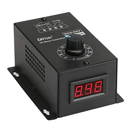
Building the frame. I designed and cut all of this on the CNC from 1/4″ 6061 Aluminum.

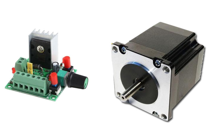
It was obvious i needed more control over the speed, so I decided to try a stepper motor driven with a stepper motor speed controller board. This worked, however again there was no precise way to dial this speed automatically, nor was there an ideal way to package the stepper motor speed control board into a usable control pad.
So I decided to invest a bit more into this and go with an Arduino controlled setup using a stepper motor.
December 2018
Going from a random fun cheap project, to serious piece of equipment.
Unfamiliar with the technical aspect of Arduino, I opted to buy plans from Minidozerbuild
They had already gone thru the process and documentation of building an Ardunio capable of driving a stepper motor for a welding positioner.
Parts Needed for the Arduino Setup
| QTY | Part | Seller | Cost |
| 1 | Digital Stepper Motor Driver 1.0-4.2A | Ebay | $24.81 |
| 1 | Nema 23 Stepper Motor | Ebay | $19.99 |
| 1 | Waterproof Junction Box | Ebay | $15.10 |
| 1 | Rotary Poteniometer (5pack) | Amazon | $5.63 |
| 1 | Arduino expansion Board | Amazon | $9.98 |
| 1 | Arduino UNO R3 | Amazon | $18.90 |
| 1 | SainSmart LCD Sheild | Amazon | $17.66 |
| 1 | 9V 1A Power Adapter | Amazon | $5.01 |
| 1 | 24vt Universal Switching Powe Supply | Amazon | $19.98 |
Unsure of the reliability of having any of the electronics grounded thru the frame of the positioner, I fabricated HMW Shims & parts to isolate the stepper motor.

The completed working setup, everything electronic has been packed into the plastic enclosure, Arduino, controls, power supply and stepper driver.


Arduino Rotary Weld Positioner
Version 2
December 2019
Now im just showing off
Now with a little Arduino experience im feeling a bit more confident with how I understand it. Ive decided it was time to take this thing to the next level. It wasent so much needed, but another test to myself of what im capable of. Also, it would just be awesome, anything awesome is just worth attempting. The original head angle position design is manual, with a spring loaded knob that’s pulled on to allow free 0-90degree movement of the head position. When the knob is pulled the head can freely move. While doing this you are required to pull the knob with one hand while supporting the head with the other. The machine must be fastened down to something otherwise it will want to flop over, the Lathe Chuck on this thing is heavy so its not an easy task, its not hard but it does take some care as not to smash or pinch your hand while doing so. Also the spring loaded lock sometimes misses the hole and requires some finesse to get locked in, while holding the heavy lathe chuck end this can be annoying.
So I come up with a plan to make this function also motorized, using the same Arduino for the rotating function of the lathe chuck.
Here I reworked the rotary drive system, removing the chain and sprocket, instead using aluminum XL timing pulley’s and XL Timing belt. This is a better option for eliminating weld electricity from reaching the stepper motor.
I also reworked the isolation bushings using Acetal Copolymer Plastic , it is much easier to work with and is a harder plastic compared to the HMW that was compressing when tightened down.

Here I used a 80:1 Stepper Worm Gear Box with a Nema 23 425oz Stepper motor. I originally intended this to be the main drive system, but it ended up not being enough gear reduction to give the torque needed, either it couldn’t lift the head or it would slip while holding the head. Instead I retrofitted the chain drive system from the rotary drive onto it , witch gave the sufficient torque to hold the head.
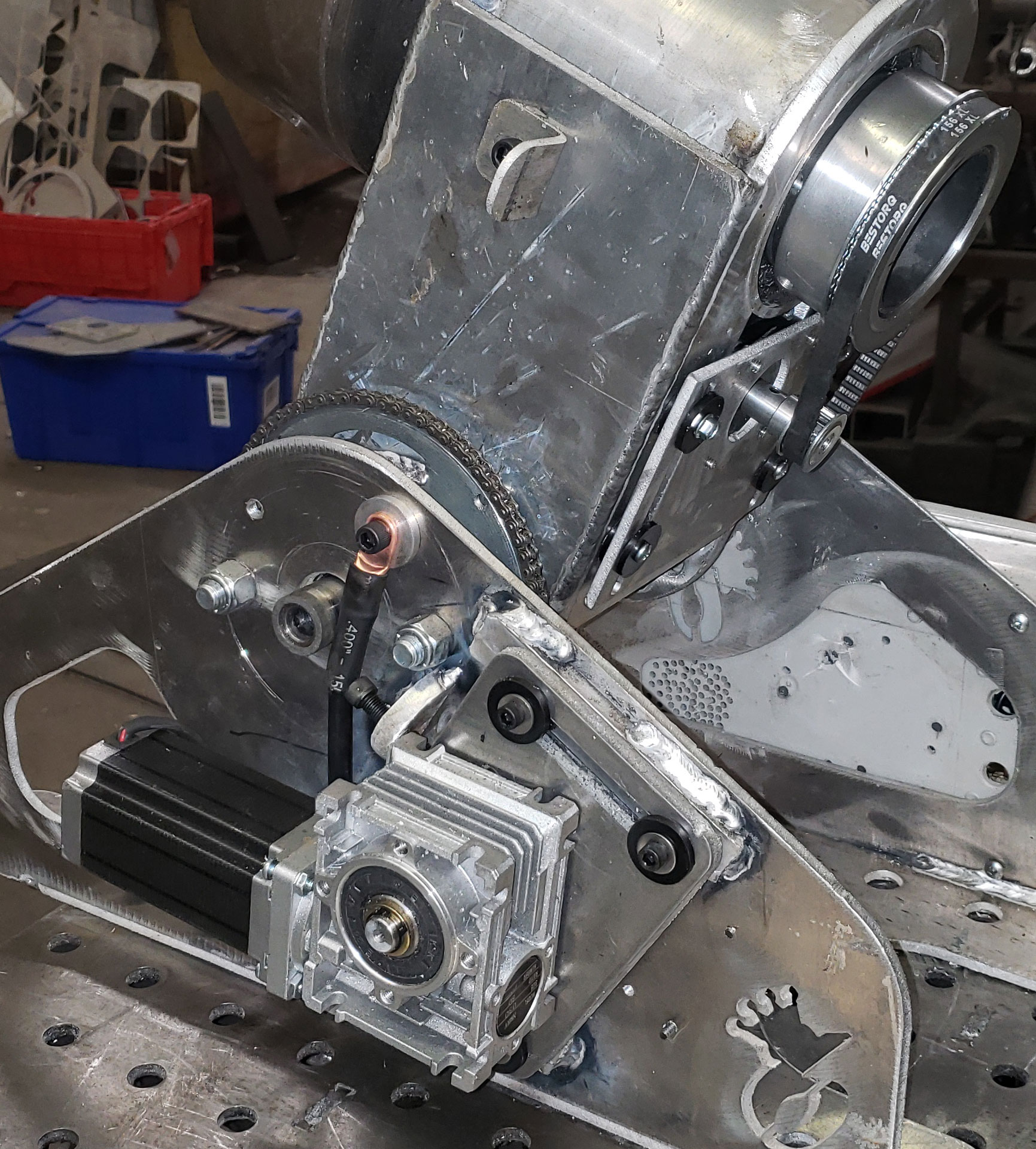
A limit switch and rubber bumper is placed in the stow position for the articulating head. A rubber bumper allows the head head to be stowed and carried without putting stress on the drive system. The limit switch is in place for when the Rotary Weld Positioner is powered off / Unplugged, when it is powered back on the Arduino begins a homing sequence,the welding positioner will return to the stowed position and reset the degrees angle on the LCD screen.
The chain drive system attached to the worm gear box, is attached with a steel drive shaft with a internal plastic bushing to isolate the motors from weld current.

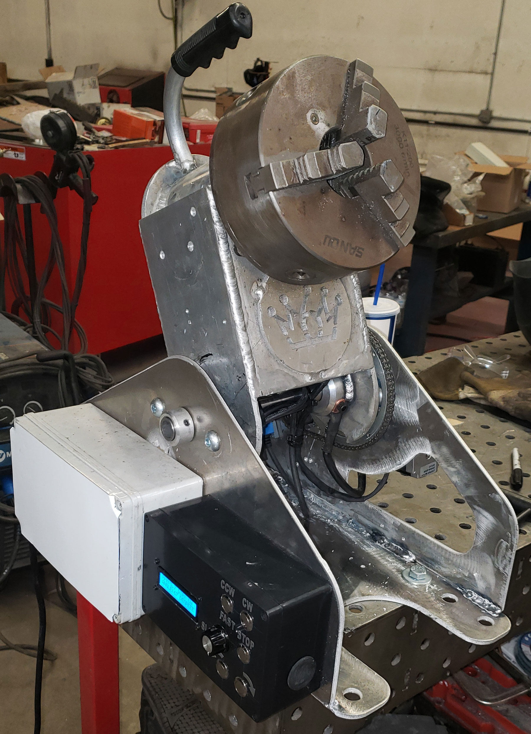
New control setup , the first line displays the speed and the current direction the head is spinning in. The second line displays the current angle the rotating head axis is positioned at.

The finished setup, both stepper drivers and power supply are mounted in the white plastic box. the Arduino and button controls mounted in the black plastic box.
A Video of the Rotary Weld Positioner In action
