September 2018
The initial build
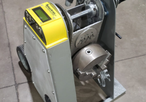
Ive had this idea to custom make a Rotary Weld Petitioner for a long time. I had originally thought to make it economically as possible for off jobs, being I didn’t have a demanding use for such a positioner, after months of researching different positioner and debating with myself about buying a Chinese made positioner found on eBay. I decided to give it ago and make one myself after having the idea I could use one of several used wiper motors I have from parts Mx6’s.
Parts Initially bought:
| QTY | Part | Seller | Cost |
| 1 | 8″ 3 Jaw Self Centering Lathe Chuck (china brand) | Ebay | $111.59 |
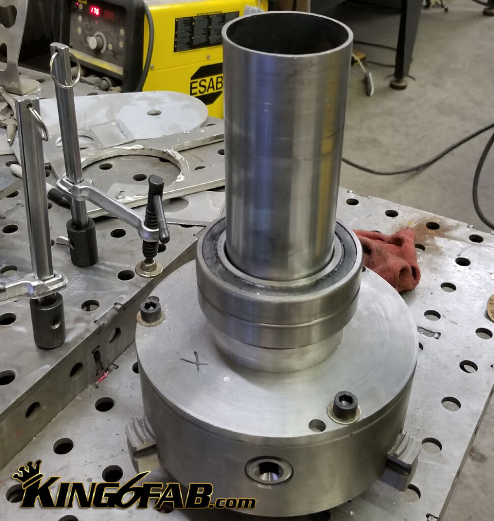
| 2 | 2.75 ID(70mm) x 4.33OD(110) x .78 (20mm) Ball Bearing Roller Bearings | Ebay | $25.12 |
| 1 | 2.75 OD x .083WA DOM Steel tubing 24in | SRI-Supplies.com | $36.18 |
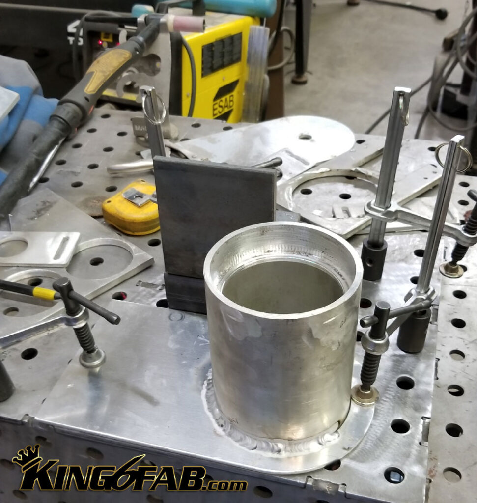
| 1 | 4-3/4 OD x 3-3/4 ID 6061 Aluminum Mechanical Tubing 12″ | Ebay | $24.50 |
| 1 | 3-3/4 OD x 2-3/4 ID 6061 Aluminum Mechanical Tubing 12″ | Ebay | $14.00 |
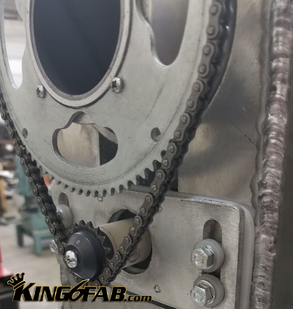
| 1 | #25 Chain 17 Tooth Sprocket | Ebay | $6.50 |
| 1 | #25 Chain 80 Tooth Sprocket | Ebay | $9.99 |
| 1 | #25 Roller Chain | Ebay | $11.99 |
| $239.87 |
The wiper motor design proved to be inconsistent in speed. I had bought a DC Speed controller that allowed to adjust the wiper motor to a crawl, but there was no consistent setting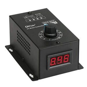 that you could automatically set it for concerning welding process of type of material. Every time you welded with it,you had to make many welding test’s to dial in the correct speed. On Some process’s the wiper motor was just to slow or to fast and no in between speed to dial it in.
Building the frame. I designed and cut all of this on the CNC from 1/4″ 6061 Aluminum.

It was obvious i needed more control over the speed, so I decided to try a stepper motor driven with a stepper motor speed controller board.  This worked, however again there was no precise way to dial this speed automatically, nor was there an ideal way to package the stepper motor speed control board into a usable control pad.
So I decided to invest a bit more into this and go with an Arduino controlled setup using a stepper motor.
December 2018
Going from a random fun cheap project, to serious piece of equipment.
Unfamiliar with the technical aspect of Arduino, I opted to buy plans from Minidozerbuild
They had already gone thru the process and documentation of building an Ardunio capable of driving a stepper motor for a welding positioner.
Parts Needed for the Arduino Setup
| QTY | Part | Seller | Cost |
| 1 | Digital Stepper Motor Driver 1.0-4.2A | Ebay | $24.81 |
| 1 | Nema 23 Stepper Motor | Ebay | $19.99 |
| 1 | Waterproof Junction Box | Ebay | $15.10 |
| 1 | Rotary Poteniometer (5pack) | Amazon | $5.63 |
| 1 | Arduino expansion Board | Amazon | $9.98 |
| 1 | Arduino UNO R3 | Amazon | $18.90 |
| 1 | SainSmart LCD Sheild | Amazon | $17.66 |
| 1 | 9V 1A Power Adapter | Amazon | $5.01 |
| 1 | 24vt Universal Switching Powe Supply | Amazon | $19.98 |
Unsure of the reliability of having any of the electronics grounded thru the frame of the positioner, I fabricated HMW Shims & parts to isolate the stepper motor.


